background image

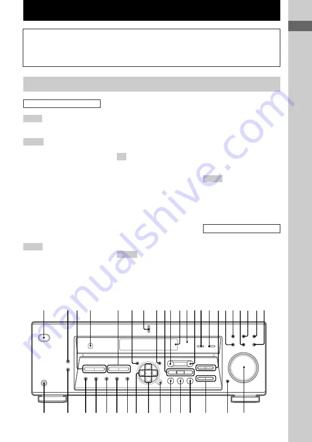
List of Button Locations and Reference Pages

5

GB

g

+

wd

wf

wh

wj

wk

wl

es

ed

ef

eg

eh

ek

ej

wg

1

7

8

4

qs

0 qa

5

2 3

6

qf qg

qj

qh

qkqlw;

qd

waws

9

e; 

ea

List of Button Locations and Reference Pages

Main unit

How to use this page

Use this page to find the location of buttons that
are mentioned in the text.

FM MODE (Models of area code

CEL, CEK only) 

ed

, (Except for

models of area code CEL, CEK)

ef

 (32)

INPUT MODE 

qg

 (22)

IR (receptor) 

4

 (39, 46, 52)

LEVEL 

0

 (16, 20, 28, 57)

M

MASTER VOLUME 

wd

 (20, 50)

MD/TAPE 

qj

 (22)

MEMORY 

eh

 (31, 33)

MENU +/– 

e;

 (16, 28, 36, 37, 57)

MENU </> 

ea

 (16, 28, 36, 37, 57)

MODE 

wj

 (25, 30, 51)

MULTI CHANNEL DECODING

(indicator) (HT-DDW840 only)

7

 (22)

MULTI CH IN (HT-DDW840

only) 

qf

 (22)

MUTING 

wf

 (22, 50)

N – S

NAME 

8

 (36)

PHONES (jack) 

ek

 (22, 51)

PRESET/PTY /–

(Models of area code CEL, CEK
only) 

3

 (33, 34)

PRESET /– (Except

for models of area code CEL,
CEK) 

3

 (33, 54)

PTY (models of area code CEL,

CEK only) 

ef

 (34)

SET UP 

6

 (4, 16, 37, 57)

SHIFT 

eg

 (33)

SLEEP (HT-DDW740 only) 

qf

(37)

SURR 

qd

 (28, 57)

T – Z

/– 

qh

 (30, 57)

TUNER 

ws

 (22, 32, 33, 36)

/– 

5

 (32)

VIDEO 1 

qk

 (22)

VIDEO 2 

w;

 (22)

BUTTON DESCRIPTIONS

`/1

 (power) 

1

 (4, 15, 20, 21,

30, 31, 54)

ALPHABETICAL ORDER

0 – 9

2 CH 

wh

 (26)

A – D

A.DEC 

wk

 (24, 26)

AM (Except for models of area

code CEL, CEK) 

es

 (31, 32)

BASS +/– 

wg

 (19, 30, 57)

CD 

ql

 (22)

CINEMA STUDIO EX A, B, C

9

 (25)

Digital Cinema Sound (indicator)

qs

 (24)

DIMMER 

ej

 (23)

DISPLAY 

2

 (23, 34, 52)

Display 

qa

 (23)

DVD/LD 

wa

 (22)

E – L

ENTER 

wl

 (36)

FM (Except for models of area

code CEL, CEK) 

ed

 (31, 32)

FM/AM (Models of area code

CEL, CEK only) 

es

 (31, 32)

Illustration number

           r

NAME      

8

 (36)

R

R

Name of button/part

Reference page

Summary of Contents for HT-DDW740

Page 1: ...d The model and serial numbers are located on the rear panel Record the serial number in the space provided below Refer to them whenever you call upon your Sony dealer regarding this product Model No HT DDW840 DDW740 Serial No 2002 Sony Corporation GB Operating Instructions ...

Page 2: ...this equipment does cause harmful interference to radio or television reception which can be determined by turning the equipment off and on the user is encouraged to try to correct the interference by one or more of the following measures Reorient or relocate the receiving antenna Increase the separation between the equipment and receiver Connect the equipment into an outlet on a circuit different...

Page 3: ...the multi channel surround displays 27 Customizing sound fields 28 Receiving Broadcasts Storing FM stations automatically AUTOBETICAL 2 31 Direct tuning 31 Automatic tuning 32 Preset tuning 32 Using the Radio Data System RDS 2 34 Other Operations Naming preset stations and program sources 36 Recording 36 Using the Sleep Timer 37 Adjustments using the SET UP button 37 Operations Using the Remote RM...

Page 4: ...n the use of your remote see pages 39 45 for RM PP411 HT DDW840 only and pages 46 49 for RM U306 HT DDW740 only Note for the supplied remote For RM PP411 HT DDW840 only The VIDEO 3 TV SAT PHONO AUX SOURCE MPX DUAL ANALOG DIRECT 12 and ON SCREEN buttons on the remote are not available For RM U306 HT DDW740 only The MULTI CH button on the remote is not available Demonstration Mode The demonstration ...

Page 5: ...MUTING wf 22 50 N S NAME 8 36 PHONES jack ek 22 51 PRESET PTY SELECT Models of area code CEL CEK only 3 33 34 PRESET TUNING Except for models of area code CEL CEK 3 33 54 PTY models of area code CEL CEK only ef 34 SET UP 6 4 16 37 57 SHIFT eg 33 SLEEP HT DDW740 only qf 37 SURR qd 28 57 T Z TREBLE qh 30 57 TUNER ws 22 32 33 36 TUNING 5 32 VIDEO 1 qk 22 VIDEO 2 w 22 BUTTON DESCRIPTIONS 1 power 1 4 1...

Page 6: ...e you get started Turn off the power to all components before making any connections Do not connect the AC power cord until all of the connections are completed Be sure to make connections firmly to avoid hum and noise When connecting an audio video cord be sure to match the color coded pins to the appropriate jacks on the components yellow video to yellow white left audio to white and red right a...

Page 7: ...end the FM wire antenna After connecting the FM wire antenna keep it as horizontal as possible IN OUT IN CD MD TAPE R L SUB WOOFER MULTI CH IN FRONT SURROUND R L CENTER ANTENNA AM FM 75Ω COAXIAL DVD LD IN COAXIAL AUDIO IN AUDIO IN AUDIO OUT AUDIO OUT AUDIO IN VIDEO 1 VIDEO IN VIDEO IN VIDEO OUT VIDEO IN VIDEO OUT DVD LD MONITOR VIDEO 2 SUB WOOFER OPTICAL VIDEO 2 IN DIGITAL The shape of the connect...

Page 8: ...COAXIAL DVD LD IN COAXIAL AUDIO IN AUDIO IN AUDIO OUT AUDIO OUT AUDIO IN VIDEO 1 VIDEO IN VIDEO IN VIDEO OUT VIDEO IN VIDEO OUT DVD LD MONITOR VIDEO 2 SUB WOOFER OPTICAL VIDEO 2 IN DIGITAL LINE L R OUTPUT A IN OUT LINE L R LINE INPUT OUTPUT ç ç A A Audio component hookups MD or Tape deck CD player ...

Page 9: ...UDIO IN OUTPUT INPUT L IN OUT Ç Ç B B AUDIO OUT VIDEO OUT L R OUTPUT B VIDEO 2 VIDEO 1 Video component hookups TV monitor DVD or LD player Note on video component hookups You can connect your TV s audio output jacks to the VIDEO 2 AUDIO IN jacks on the receiver and apply sound effects to the audio from the TV In this case do not connect the TV s video output jack to the VIDEO 2 VIDEO IN jack on th...

Page 10: ... sound of a movie theater into your home To fully enjoy multi channel surround sound five speakers two front speakers two surround speakers and a center speaker and a sub woofer are required You can also connect an LD player with an RF OUT jack via an RF demodulator like the Sony MOD RF1 not supplied Notes You cannot connect an LD player s DOLBY DIGITAL RF OUT jack directly to this unit s digital ...

Page 11: ...n Dolby Digital and DTS If your DVD player is equipped with multi channel output jacks you can connect them directly to the receiver to enjoy the sound of the DVD player s multi channel decoder Alternatively the multi channel input jacks can be used to connect an external multi channel decoder To fully enjoy multi channel surround sound five speakers two front speakers two surround speakers and a ...

Page 12: ...g the voltage selector If your receiver has a voltage selector on the rear panel check that the voltage selector is set to the local power supply voltage If not use a screwdriver to set the selector to the correct position before connecting the AC power cord to a wall outlet 120V 240V 220V VOLTAGE SELECTOR VOLTAGE SELECTOR FRONT CENTER SURROUND R L R L R L R L SPEAKERS SPEAKERS IMPEDANCE USE 8 16Ω...

Page 13: ...16Ω FRONT R L R L E e E e A A INPUT AUDIO IN B E e E e E e A A A IMPEDANCE USE 8 16Ω Hooking Up and Setting Up the Speaker System Front speaker L Front speaker R Center speaker Surround speaker L Surround speaker R Active sub woofer continued Speaker system hookups Required cords A Speaker cords supplied B Monaural audio cord supplied Black Black ...

Page 14: ...s Make sure the stripped ends of each speaker cord does not touch another speaker terminal the stripped end of another speaker cord or the metal parts of the receiver Examples of poor conditions of the speaker cord Stripped speaker cord is touching another speaker terminal Stripped cords are touching each other due to excessive removal of insulation After connecting all the components speakers and...

Page 15: ...s of preset stations and program sources are cleared All SET UP parameters are reset to their factory settings The sound field memorized for each program source and preset stations are cleared The master volume is set to VOL MIN Performing initial setup operations Before using your receiver for the first time adjust SET UP parameters so that the receiver correspond to your system For the adjustabl...

Page 16: ... then turn on again while pressing LEVEL To reset to MICRO SP do the same procedure Tip The setting for Micro Satellite Speaker MICRO SP has been programmed to optimize the sound balance If you use Sony s Micro Satellite Speakers select MICRO SP Caution When you use Micro Satellite Speakers and the speaker size is set to LARGE you may not obtain the correct soundstage The speaker may also be damag...

Page 17: ...eters 15 feet closer This is because incorrect speaker placement is not conducive to enjoy surround sound Please note that setting the speaker distance closer than the actual location of the speakers will cause a delay in the output of the sound from that speaker In other words the speaker will sound like it is farther away For example setting the center speaker distance 1 2 m 3 6 feet closer than...

Page 18: ...round speaker height SL SR HGT XXX This parameter lets you specify the height of your surround speakers for proper implementation of the Digital Cinema Sound surround modes Refer to the illustration below Select LOW if the location of your surround speakers corresponds to section A Select HIGH if the location of your surround speakers corresponds to section B These parameters are not available whe...

Page 19: ... channel bass frequencies from the sub woofer or other LARGE speakers If you do not connect surround speakers select NO 3 Tip 1 3 correspond to the following Dolby Pro Logic modes 1 NORMAL 2 PHANTOM 3 3 STEREO Tip Internally the LARGE and SMALL settings for each speaker determine whether or not the internal sound processor will cut the bass signal from that channel When the bass is cut from a chan...

Page 20: ... tone cannot be output when the receiver is set to MULTI CH IN HT DDW840 only The adjusted value are shown in the display during adjustment Although these adjustments can also be made via the front panel using the LEVEL menu when the test tone is output the receiver switches to the LEVEL menu automatically we recommend you follow the procedure described above and adjust the speaker levels from you...

Page 21: ...ctions were made correctly 1 Press 1 to turn on the receiver 2 Turn on the component that you connected e g CD player or tape deck 3 Press the function button to select the component program source 4 Start playing If you do not obtain normal sound output after performing this procedure see Troubleshooting on page 50 and take the appropriate measures to correct the problem ...

Page 22: ...ted COAX IN Specify the digital audio signals input to the DIGITAL COAXIAL input jacks Select To OPT IN Specify the digital audio signals input to the DIGITAL OPTICAL input jacks ANALOG Specify the analog audio signals input to the AUDIO IN L R jacks Note If 96 kHz digital signal is input the tone sound field and surround parameters do not function MULTI CH IN HT DDW840 only Press MULTI CH IN to e...

Page 23: ...indication t Radio text t Current time t Sound field applied to the band or the preset station Index name appears only when you have assigned one to the component or preset station page 36 Index name does not appear when only blank spaces have been entered or it is the same as the function During RDS reception only Models of area code CEL CEK only See page 34 DIMMER Press DIMMER repeatedly to adju...

Page 24: ...y signal for output to the sub woofer Selecting a sound field You can enjoy surround sound simply by selecting one of the pre programmed sound fields according to the program you want to listen to Sound field Display Normal Surround NORM SURR Cinema Studio EX A C ST EX A D C S Cinema Studio EX B C ST EX B D C S Cinema Studio EX C C ST EX C D C S Hall HALL Jazz Club JAZZ Live Concert CONCERT Game G...

Page 25: ...nside the image reflected on the movie screen This element creates the same sensation in your listening room by shifting the sound of the front speakers into the screen Cinema Studio Reverberation Reproduces the reverberations peculiar to a movie theater Cinema Studio EX is the integrated mode which operates these elements simultaneously Tip You can select Cinema Studio EX by pressing MODE repeate...

Page 26: ... the sound from the front left and right speakers only Standard 2 channel stereo sources completely bypass the sound field processing Multi channel surround formats are downmixed to 2 channel Notes No sound is output from the sub woofer when 2CH ST is selected To listen to 2 channel stereo sources using the front left and right speakers and a sub woofer press A DEC to select AUTO DEC When you sele...

Page 27: ... surround components obtained by Pro Logic processing Example Recording format Front Surround 3 2 Output channel Surround speakers absent Sound Field AUTO DEC 1 DIGITAL Lights up when the receiver is decoding signals recorded in the Dolby Digital format 2 PRO LOGIC Lights up when the receiver applies Pro Logic processing to 2 channel signals in order to output the center and surround channel signa...

Page 28: ...fore you customize a sound field Adjusting the surround parameter The SURR menu contains parameter that let you customize various aspects of the current sound field The settings are stored individually for each sound field 1 Start playing a program source encoded with multi channel surround sound 2 Press SURR The button lights up and the first parameter is displayed 3 Press MENU or MENU to select ...

Page 29: ...t to the sub woofer from the front center or surround channels via the Dolby Digital or DTS bass redirection circuitry For LFE mix level 0 dB outputs the full LFE signal at the mix level determined by the recording engineer To mute the sound of the LFE channel from the sub woofer select OFF However the low frequency sounds of the front center or surround speakers are output from the sub woofer acc...

Page 30: ...d automatically Initial settings Parameter Initial setting BASS 0 dB TREB 0 dB Bass BASS Lets you adjust the bass tone Treble TREB Lets you adjust the treble tone Note When you use the Micro Satellite Speakers or other small speakers adjust LEVEL on the subwoofer page 20 to reinforce the bass Resetting customized sound fields to the factory settings 1 If the power is on press 1 to turn off the pow...

Page 31: ... display momentarily and the receiver returns to the normal operation Notes Do not press any button on the receiver or supplied remote during autobetical operation If you move to another area repeat this procedure to store stations in your new area For details on tuning the stored stations see page 33 If you move the antenna after storing stations with this procedure the stored settings may no lon...

Page 32: ...3 AR MX 50 kHz 9 kHz The AM tuning scale can be changed page 54 Automatic tuning If you don t know the frequency of the station you want you can let the receiver scan all available stations in your area 1 Press TUNER The last received station is tuned in 2 Press FM or AM to select the FM or AM band 3 Press TUNING or TUNING Press TUNING to scan from low to high press TUNING to scan from high to low...

Page 33: ...RESET PTY SELECT or PRESET PTY SELECT To change a preset number to another station Do steps 1 to 6 to preset a new station to the number Tuning to preset stations You can tune the preset stations by either of the following two ways Scanning the preset stations 1 Press TUNER The last received station is tuned in 2 Press PRESET TUNING or PRESET TUNING repeatedly to select the preset station you want...

Page 34: ...m which enables radio stations to send additional information along with the regular program signal You can use the following convenient RDS features Displaying RDS information Scanning preset stations by program type Note that RDS is operable only for FM stations Not all FM stations provide RDS service nor do they provide the same types of services If you are not familiar with the RDS services in...

Page 35: ... SPORT Sports programs EDUCATE Educational programs such as how to and advice programs DRAMA Radio plays and serials CULTURE Programs about national or regional culture such as language and social concerns SCIENCE Programs about the natural sciences and technology VARIED Other types of programs such as celebrity interviews panel games and comedy POP M Popular music programs ROCK M Rock music progr...

Page 36: ...press MENU to move the cursor to the next position To insert a space Press MENU or MENU until a blank space appears in the display If you ve made a mistake Press MENU or MENU repeatedly until the character to be changed flashes then press MENU or MENU to select the right character 4 Press ENTER 5 Repeat steps 2 to 4 to assign index name for another station or program source Note Models of area cod...

Page 37: ...R a TV a DVD player or an LD player using the receiver You can also add audio from a variety of audio sources when editing a video tape See the operating instructions of your VCR or LD player if you need help 1 Select the program source to be recorded 2 Prepare the component for playing For example insert the laser disc you want to record into the LD player 3 Insert a blank video tape into the VCR...

Page 38: ...d in 5 1 channel through Dolby Pro Logic II When set to DOLBY PL the receiver performs the Pro Logic decoding The source recorded in 2 channel is decoded into 4 channels When set to II MOVIE the receiver performs the Pro Logic II movie mode decoding This setting is ideal for the movies encoded in Dolby Surround Besides this mode can reproduce the sound in 5 1 channel when watching the videos of ol...

Page 39: ...d period of time remove the batteries to avoid possible damage from battery leakage and corrosion Remote button description N X m M VIDEO1 VIDEO2 USE MODE SYSTEM STANDBY SLEEP AV1 AV2 TV 1 AV 1 VIDEO3 DVD LD TV SAT MD TAPE CD SACD TUNER PHONO AUX MULTI CH SOURCE SHIFT TOP MENU GUIDE AV MENU MUTING MASTER VOL DISPLAY TV VOL TV CH WIDE ON SCREEN TV VIDEO MAIN MENU RETURN EXIT D TUNING DISC ALT ANT C...

Page 40: ...set stations D TUNING Receiver Tuner station direct key in mode MUTING Receiver Mutes the sound from the receiver Remote Operations Function Button V v Receiver Select a menu item B b Receiver Makes adjustment or change the setting MASTER Receiver Adjusts the master VOL volume of the receiver MAIN Receiver Press this button MENU repeatedly to select one of the four cursor modes SURR LEVEL SET UP a...

Page 41: ...ctly VCD player multi disc changer only ANT VCR Selects output signal from aerial terminal TV signal or VCR program VCR Skips tracks CD player VCD player LD player DVD player MD deck DAT deck Tape deck Only for Sony TVs with the picture in picture function Remote Operations Function Button m M CD player Searches tracks VCD player forward or backward DVD player LD player MD deck VCR Fastforwards or...

Page 42: ...e key function to activate those buttons with orange printing Notes Some functions explained in this section may not work depending on the model of the receiver The above explanation is intended to serve as an example only Therefore depending on the component the above operation may not be possible or may operate differently than described The VIDEO 3 TV SAT PHONO AUX SOURCE MPX DUAL ANALOG DIRECT...

Page 43: ...de has been verified the indicator slowly flashes twice and the remote automatically exits the programming mode 5 Repeat steps 1 to 4 to control other components To cancel programming Press USE MODE during any step The remote automatically exits the programming mode To activate the function after programming Press the programmed button to activate the function you want If programming is unsuccessf...

Page 44: ...pond to some or all of the codes All of the functions on this remote may not be available when used with your particular component To control a CD player Maker Code s SONY 101 102 103 DENON 104 123 JVC 105 106 107 KENWOOD 108 109 110 MAGNAVOX 111 116 MARANTZ 116 ONKYO 112 113 114 PANASONIC 115 PHILIPS 116 PIONEER 117 TECHNICS 115 118 119 YAMAHA 120 121 122 Programming the remote continued To contr...

Page 45: ...747 755 756 ZENITH 754 To control a DVD player Maker Code s SONY 401 402 403 PANASONIC 406 408 PHILIPS 407 PIONEER 409 TOSHIBA 404 DENON 405 To control a TV Maker Code s SONY 501 DAEWOO 504 505 506 507 515 544 FISHER 508 GOLDSTAR 503 511 512 515 534 544 GRUNDIG 517 534 HITACHI 513 514 515 544 ITT NOKIA 521 522 JVC 516 MAGNAVOX 503 518 544 MITSUBISHI MGA 503 519 544 NEC 503 520 544 PANASONIC 509 52...

Page 46: ...the remote in an extremely hot or humid place Do not use a new battery with an old one Do not expose the remote sensor to direct sunlight or lighting apparatuses Doing so may cause a malfunction If you don t use the remote for an extended period of time remove the batteries to avoid possible damage from battery leakage and corrosion Remote button description N X m M 1 2 3 4 5 6 7 8 0 9 MD TAPE CD ...

Page 47: ...er disc or track usng the LD player numeric buttons press MD deck to enter the value DAT deck Tape deck RETURN VCD player Go back to previous menu The tables below show the settings of each button Remote Operations Function Button SLEEP Receiver Activates the sleep function and the duration which the receiver turns off automatically 1 Receiver Turns the receiver on or off VIDEO 1 Receiver To watch...

Page 48: ...r The above explanation is intended to serve as an example only Therefore depending on the component the above operation may not be possible or may operate differently than described The MULTI CH function is not available for set operation Remote Operations Function Button CH Receiver Scans and selects preset PRESET stations TV VCR Selects preset channels satellite tuner VCR Skips tracks CD player...

Page 49: ... the component you want to assign to the Function button for example 4 Tape deck The following buttons are assigned to select the functions To operate Press CD player 1 DAT deck 2 MD deck 3 Tape deck A 4 Tape deck B 5 LD player 6 VCR command mode VTR 1 7 VCR command mode VTR 2 8 VCR command mode VTR 3 9 TV 0 DSS Digital Satellite Receiver 10 DVD ENTER VCD player Sony VCRs are operated with a VTR 1...

Page 50: ...ashes Turn off the receiver eliminate the short circuit problem and turn on the power again Precautions On safety Should any solid object or liquid fall into the cabinet unplug the receiver and have it checked by qualified personnel before operating it any further On power sources Before operating the unit check that the operating voltage is identical with your local power supply The operating vol...

Page 51: ...loth slightly moistened with alcohol There is no sound or only a very low level sound is heard from the center or and surround speaker Make sure the sound field function is on press MODE Select a sound field containing the word C ST EX pages 24 25 Adjust the speaker level page 20 Make sure the center or and surround speaker size parameter is set to either SMALL or LARGE page 16 There is no sound f...

Page 52: ...service in question If so the service may be temporarily out of order There is no picture or an unclear picture appears on the TV screen or monitor Select the appropriate function on the receiver Set your TV to the appropriate input mode Move your TV away from the audio components The remote does not function The VIDEO3 TV SAT PHONO AUX SOURCE MPX DUAL ANALOG DIRECT 12 and ON SCREEN buttons on the...

Page 53: ...0 W ch STR K740P FRONT1 80 W ch CENTER1 80 W SURR1 80 W ch Models of area code AR SP Rated Power Output at Stereo Mode 8 ohms 1 kHz THD 0 7 STR K840P 90 W 90 W2 continued Reference Power Output2 8 ohms 1 kHz THD 10 STR K840P FRONT1 120 W ch CENTER1 120 W SURR1 120 W ch Models of other area code Rated Power Output at Stereo Mode 8 ohms 1 kHz THD 0 7 STR K840P 100 W 100 W2 STR K740P 80 W 80 W2 Refer...

Page 54: ...AR MX With 10 kHz tuning scale 530 1610 kHz6 With 9 kHz tuning scale 531 1602 kHz6 Models of area code SP CEL CEK With 9 kHz tuning scale 531 1602 kHz Antenna Loop antenna Intermediate Frequency 450 kHz Usable sensitivity 50 dB m at 1 000 kHz or 999 kHz S N 54 dB at 50 mV m Harmonic distortion 0 5 50 mV m 400 Hz Selectivity At 9 kHz 35 dB At 10 kHz 40 dB 6 You can change the AM tuning scale to 9 k...

Page 55: ...s Power handling capacity Maximum input power 100 W Sensitivity level 85 dB 1 W 1 m Frequcency range 160 Hz 20 000 Hz Dimensions w h d SS MSP2 Approx 81 141 121 mm 3 1 4 5 5 8 4 7 8 inches SS CNP2 Approx 230 81 121 mm 9 1 8 3 1 4 4 7 8 inches Mass SS MSP2 0 8 kg 1 lb 13 oz SS CNP2 1 0 kg 2 lb 4 oz SA WMSP4 for HT DDW840 SA WMSP2 for HT DDW740 AUDIO POWER SPECIFICATIONS POWER OUTPUT AND TOTAL HARMO...

Page 56: ...antenna 1 AM loop antenna 1 Speaker connecting cord long 2 Speaker connecting cord short 3 Monaural connecting cord 1 phono to 1 phono 1 Coaxial digital cord 1 Foot pads speakers 20 Foot pads subwoofer 4 Remote commander 1 RM PP411 HT DDW840 only RM U306 HT DDW740 only R6 size AA batteries 2 Speakers Front speakers 2 Surround speakers 2 Center speaker 1 Subwoofer SA WMSP4 HT DDW840 only 1 Subwoofe...

Page 57: ... 16 C CENTER 1 LARGE SMALL NO SL SR SURROUND 1 LARGE SMALL NO SW SUB WOOFER S W XXX1 YES NO L R DIST XX X m between 1 0 meters and 12 0 meters 0 1 meters steps 2 C DIST XX X m between L R DIST and 1 5 meters 0 1 meters steps 3 SL SR DIST XX X m between L R DIST and 4 5 meters 0 1 meters steps 4 SL SR PL XXX SIDE MID BEHD SL SR HGT XXX LOW HIGH C MODE AVX AV1 AV2 37 PRO LOGIC 5 DOLBY PL MOVIE MUSIC...

Page 58: ...ee each item in Adjusting the level parameters page 28 3 When these sound fields are selected there is no sound output from the sub woofer if the front speaker size is set to LARGE However sound will be output from the sub woofer if the digital input signal contains L F E signals SURR BASS TREBLE EFFECT LEVEL 2CH ST z z AUTO DEC z z NORM SURR z z C ST EX A z z z C ST EX B z z z C ST EX C z z z HAL...

Page 59: ...Additional Information 59GB Sony Corporation Printed in Malaysia ...

Reviews: