background image

13(J)

仕様

一般

電源

DC10.5〜 17.0V (カメラから供給)

消費電力

50W

使用温度

−20℃〜 45℃

質量

7.9kg(フード含まず)

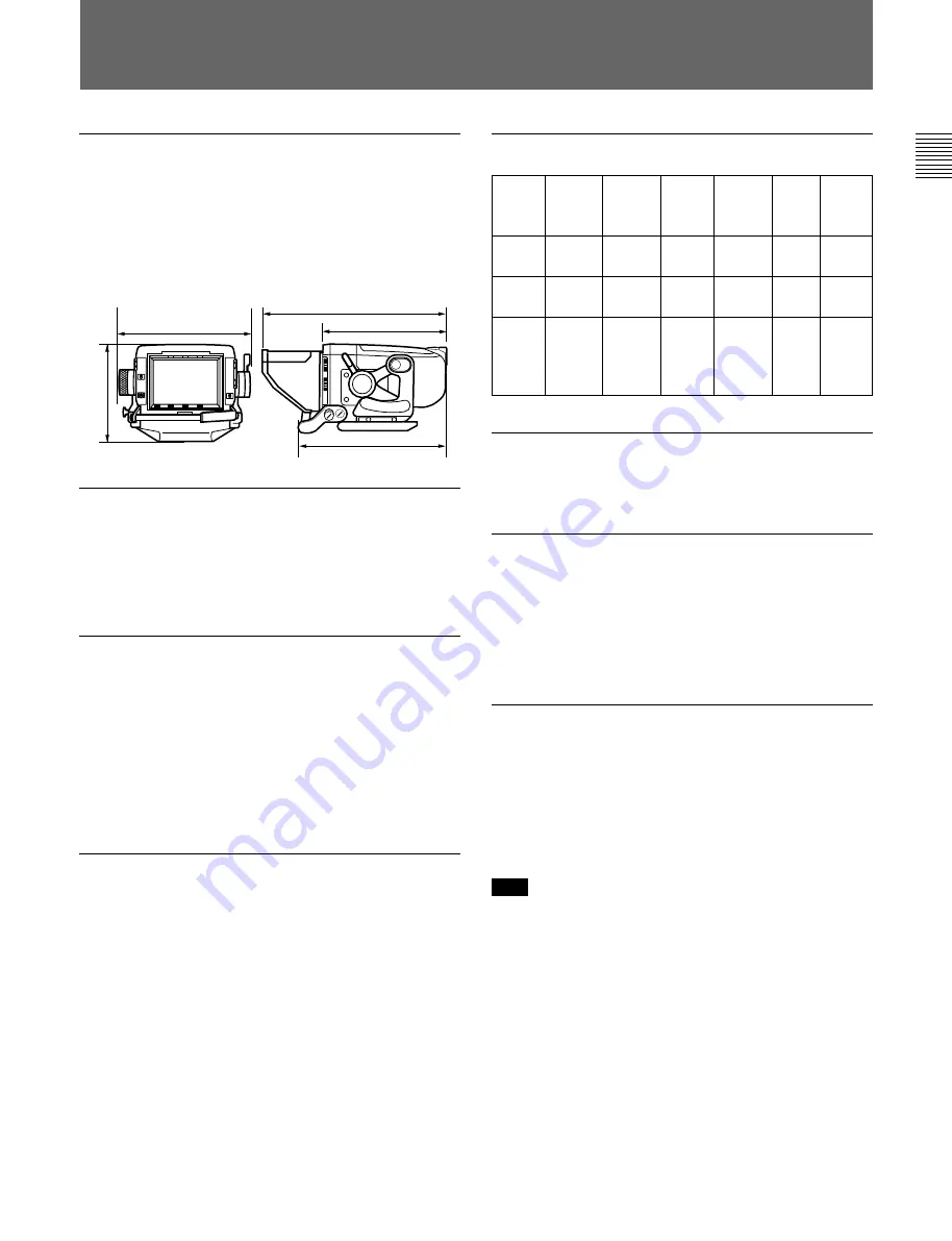
外形寸法(単位:mm)

CRT

90 度偏向 9 型スーパーファインピッチトリニトロン管

有効画面

155.4×87.4mm(水平 / 垂直、アスペクト比

16:9)

偏向および高圧系

輝度

250cd/m

2

解像度

340 本

画面ひずみ

2.0% 以下

高圧レギュレーション

±1% 以内

高圧電圧

16kV(標準)

入力電圧および信号特性

ビデオ入力

1.0 Vp-p± 6dB (SMPTE 274M)、

75 Ω終端

直流再生

バックポーチタイプ

バックポーチレベル:ピーク値 2% 以下、

平均値 10% 〜 90%

周波数特性

0.1〜 25MHz (± 3dB)

ピーキング

0dB 〜 18dB (15MHz)

同期

引き込み範囲:水平±500Hz 以上、垂直

−10Hz 以上

水平保持範囲:± 500Hz 以上

対応信号フォーマット

290

192

435

375

325

システ

ム名称

走査線

総数

/

フレーム

有効走査

線数

/

フレーム

フレーム

レート

(Hz)*

スキャン

方式

アスペ

クト比

スタン

ダード

1080/

48I

1125

1080

24

2:1

interlace

16:9

SMPTE

274M

1080/

50I

1125

1080

25

2:1

interlace

16:9

SMPTE

274M

1080/

60I

1125

1080

30

2:1

interlace

16:9

SMPTE

274M/

BTA S-

001B

接続端子

CAMERA 端子

D-sub 25ピン

付属品

屋内フード(1)

屋外フード(1)

ナンバープレート(1)

オペレーションマニュアル(1)

関連製品

HDカラービデオカメラHDC-900/910

本機の仕様および外観は、改良のため予告なく変更することがあ

りますが、ご了承ください。

重要

機器の名称と電気定格は、底面に表示されています。

..............................................................................................................................................................................................................................................................

* フレームレート1/100Iにも対応

Summary of Contents for HDVF-9900

Page 1: ...F 9900 電気製品は 安全のための注意事項を守らないと 火災や人身事故になることがあります このオペレーションマニュアルには 事故を防ぐための重要な注意事項と 製品の取り扱いかたを示してあります このオペレーションマニュアルを よくお読みのうえ 製品を安全にお使いください お読みになったあと は いつでも見られるところに必ず保管してください OPERATION MANUAL Japanese English 1st Edition Revised 1 ...

Page 2: ...たは営業担当者 にご相談く ださい 故障したら使用を中止する ソニーのサービス担当者または営業担当者にご連絡く ださい 万一 異常が起きたら 1 カメ ラの電源を切る 2 カメ ラから本製品をはずす 3 ソニーのサービス担当者 または営業担当者に修 理を依頼する すぐにカメ ラの電源を切り 消火する 警告表示の意味 このオペレーションマニュアル および製品では 次のような表 示をしています 表示の内容を よく理解してから本文をお読み ください この表示の注意事項を守らない と 火災や感電などにより死亡 や大けがなど人身事故につなが ることがあります この表示の注意事項を守らない と 感電やその他の事故により けがをしたり周辺の物品に損害 を与えたりすることがありま す 注意を促す記号 行為を禁止する記号 行為を指示する記号 炎が出たら 異常な音 におい 煙 が出たら 落下させた ら 安全の...

Page 3: ...1 J 目次 2 J 2 J 概要 3 J 各部の名称と働き 4 J カメラに取り付ける 7 J 位置を調節する チルティング操作 9 J 画面を調整する 10 J アクセサリーを取り付ける 11 J 仕様 13 J 日 本 語 ...

Page 4: ... 水や異物が入る と火災の原因となり ます 万一 水や異物が入ったときは すぐにカメ ラの電源を切り カメ ラから本製品を はずし ソニーのサービス担当者または営業担当者にご相談く ださい 油煙 湯気 湿気 ほこりの多い場所では設置 使用しない 上記のよう な場所で設置 使用する と 火災や感電の原因となり ます 下記の注意を守らないと 火災や感電により死亡や大けがにつながることがあります ビューファインダーの取り付けは確実に行う ビューフ ァイ ンダーは確実に固定してく ださい 正しく 取り付けられていないと 落 下してけがの原因となる こ とがあ り ます 下記の注意を守らないと けがをしたり周辺の物品に損害を与えることがあります ...

Page 5: ...れます 連続可変ピーキング補正 連続可変ピーキング補正回路によ り シャープな画像が得られ カ メ ラのピン ト合わせが容易です マルチフォーマット対応 1080 60i 1080 59 94i 1080 50i 1080 24Psf 48i の4つの フォーマッ ト に対応しています タリーランプ タ リ ー信号によって点灯する2系統 レッ ドおよびグリ ーン のタ リ ー ラ ンプを備えています 優れた操作性 高さ を3段階に設定でき チルティ ング角度は 最大上方向に50 下方向に45 まで変える こ とができます 防滴構造 多少の雨にも耐え られる防滴構造によ り 戸外での撮影にも適して います スタジオ用屋内フードおよびOB用屋外フードを 取り付け可能 堅牢で操作性のよいス タジオ用屋内フー ド 付属 と 遮光性に優 れているOB用屋外フー ド 付属 を取り付ける こ とができま...

Page 6: ...み qs TALLY ON OFFスイッチ qd グリーンタリーランプ 後面 前面 2 PEAKINGつまみ 3 PEAKINGスイッチ 4 フリクション調節ノブ 5 リフトロック解除ノブ 6 POWERスイッチ 7 ランプ qf 外部タリーランプ 底面 パンベースの裏側 qg ファン qh CAMERA端子 qj マウントウェッジ 底面 qk FAN STOPボタン ql R G TALLY LOWER スイッチ w R G TALLY LEVELスイッチ 1 FAN STOPアラーム wa DIMMERボリューム ...

Page 7: ...8 レッドタリーランプ カメ ラにレ ッ ドタ リ ー信号が供給される と点灯 赤 します 9 BRIGHT 明るさ調整 つまみ 画面の明る さ 輝度 を調節します 0 ロックレバー 本機を希望の角度に固定する レバーです レバーをカメ ラのレンズ 側に倒すと固定され 手前に倒すと フ リ クシ ョ ン調節ノブ 4で調 整されたフ リ クシ ョ ンで角度を調節できます qa CONTRAST コントラスト調整 つまみ 画面のコン ト ラス ト を調節します qs TALLY ON OFF 外部タリーランプオン オフ スイッチ 外部タ リ ーラ ンプ qfをコ ン ト ロールします ON タ リ ーラ ンプが機能する OFF タ リ ーラ ンプが機能しない レッ ドタ リ ー信号がカメ ラに供 給されても 点灯しません qd グリーンタリーランプ カメ ラにグリ ーンタ リ ー信号が供給され...

Page 8: ...プ qdを選択します ON すべてのレッ ドおよびグリ ーンタ リ ーラ ンプを点灯させる OFF ビューフ ァイ ンダー上部のレ ッ ドおよびグリ ーンタ リ ーラ ン プのみを点灯させる w R G TALLY LEVEL レッド グリーンタリーランプ光 量調節 スイッチ レッ ドタ リ ーラ ンプ 8およびグリ ーンタ リ ーランプ qdの光量を調節 します H 明る く 点灯 M 通常の点灯 L 暗く 点灯 wa DIMMER 外部タリー光量調節 ボリューム 調整用 ドライ バーなどを差し込んで外部タ リ ーラ ンプ qfの光量を 調整できます 右方向に回すと明る く なり 左方向に回すと暗く なり ます ...

Page 9: ...いては 位置を調節する チルテ ィ ング 操作 9 J ページ の手順をご覧く ださい ビューファインダーの取り付けかた 1 カメ ラのパンベース受け台を 上図の位置まで右方向いっぱ いに回転させる 2 ビューフ ァイ ンダーのパンベース裏側にあるマウ ン ト ウェ ッ ジが カメ ラのパンベース受け台のV字型溝の中に入るよう に ま た パンベース裏側の突起部が図に示す位置にく るように ビューフ ァイ ンダーをパンベース受け台にのせる 3 ハン ドルを押して ビューフ ァイ ンダーをパンベース受け台に しっかり と差し込む ハン ドルを引っ張り 確実に固定されている こ とを確認してく ださ い 4 ビューフ ァイ ンダーを任意の位置に回転させる ビューフ ァイ ンダーは確実に固定してく ださい 正しく 取り付け られていないと 落下してけがの原因となる こ とがあ り ます ...

Page 10: ...ロックレバーが右いっぱいの位置にある つまみ 取り外すときは 取り外す前に 次の2点を確認してく ださい ビューフ ァイ ンダーのリ フ ト解除ノ ブが一番低い位置にある こ と ビューフ ァイ ンダーのロ ッ ク レバーが右いっぱいの位置にある こ と ビューファインダーの取り外しかた 1 ビューフ ァイ ンダーを 右方向いっぱいに回転させる 2 つまみを押しながら ビューフ ァイ ンダーのハン ドルを手前に引 き 持ち上げて外す カメラに取り付ける ...

Page 11: ...き下げ ロ ッ ク レバーをレンズ側に倒し てく ださい また リ フ ト ロ ッ ク解除ノ ブが 標準位置の溝にはまっ ている ことを確認してく ださい 1 ロ ック レバーを手前に倒す 2 リ フ ト ロック解除ノ ブを引っぱり ながら 本機のハン ドルを持っ て 本機を最高位置または中間位置まで引き上げる ご注意 このとき リ フ ト ロ ック解除ノ ブのみを持って引き上げる と 高さ 設定が正常にロ ッ ク されないと きがあ り ますので 必ずハン ド ルを持って引き上げてく ださい 3 フ リ クシ ョ ン調節ノ ブを回して フ リ クシ ョ ンを調節する 右に回すと動きが重く なり 左に回すと軽く なり ます 4 チルティ ング角度を調節する チルティ ング角度を調節した後は ロ ッ ク レバーをカメ ラのレン ズ側に倒してロ ッ ク します リフトロック解除ノブ 重くなる ...

Page 12: ...があ り ますのでご注意く ださい 2 CONTRASTつまみを回して 画面のコン ト ラス ト を調節する 3 PEAKING切り換えスイ ッチをONにする 4 PEAKINGつまみを回して ピーキングを補正する 輪郭をはっき り と させるには 時計方向に回します ハンドルを下げるには ハン ドルは 下の方向に約30 まで下げる こ とができ ます 1 ハン ドルの左右についているネジを 両方と もゆるめる 2 ハン ドルを押し下げる 3 ハン ドルの左右のネジを コイ ンなどでしっかり締めて固定す る ご注意 ハン ドルが下がった状態のまま本機を回転させる と カメ ラ本体と 接触する ことがあ り ます 1 2 3 ...

Page 13: ...11 J アクセサリーを取り付ける フードを取り付けるには スタジオ用屋内フー ド 付属 の取り付けかたを説明します OB用屋外フー ド 付属 の取り付けかたも同じです 1 溝に引っかけて 取り付ける 2 ネジを回して固定する 屋内フー ドは上方向へ30 屋外フー ドは上下25 ずつ向き を変える こ とができます 屋内フード ネジ 溝 ...

Page 14: ...12 J 1 コインネジ ナンバープレート 外部タリーランプ OB用屋外フード 付属 屋外フー ドが動きにく いときや 逆に所定の位置に留ま りにく いと きは 両側にあるコイ ンネジで調節します 右に回すと動きが重く なり 左 へ回すと軽く なり ます ナンバープレートを取り付けるには ナンバープレー ト 付属 の左右のつめを外部タ リ ーラ ンプの溝に差し込みます アクセサリーを取り付ける ...

Page 15: ...Hz 3dB ピーキング 0dB 18dB 15MHz 同期 引き込み範囲 水平 500Hz以上 垂直 10Hz以上 水平保持範囲 500Hz以上 対応信号フォーマット 290 192 435 375 325 システ ム名称 走査線 総数 フレーム 有効走査 線数 フレーム フレーム レート Hz スキャン 方式 アスペ クト比 スタン ダード 1080 48I 1125 1080 24 2 1 interlace 16 9 SMPTE 274M 1080 50I 1125 1080 25 2 1 interlace 16 9 SMPTE 274M 1080 60I 1125 1080 30 2 1 interlace 16 9 SMPTE 274M BTA S 001B 接続端子 CAMERA端子 D sub 25ピン 付属品 屋内フー ド 1 屋外フー ド 1 ナンバープレー ト 1 ...

Page 16: ...equipment The shielded interface cable recommended in this manual must be used with this equipment in order to comply with the limits for a digital device pursuant to Subpart B of Part 15 of FCC Rules For the customers in Europe This product with the CE marking complies with the EMC Directive 89 336 EEC issued by the Commission of the European Community Compliance with this directive implies confo...

Page 17: ...nglish Table of Contents Overview 2 E Location and Function of Parts 3 E Attaching to the Camera 6 E Adjusting the Position Tilting 8 E Adjusting the Screen 9 E Attaching Accessories 10 E Specifications 12 E ...

Page 18: ...it provides a sharp image making it easy to focus the camera Multi format compatibility The viewfinder supports the following signal formats 1080 60i 1080 59 94i 1080 50i 1080 24Psf 48i Tally lamps The viewfinder has red and green tally lamps which light in response to tally signals Superior usability The viewfinder height may be set to one of three positions and it may be tilted up to 50º upwards...

Page 19: ... indicator 8 Red tally lamps 9 BRIGHT control 0 Lock lever qa CONTRAST control qs TALLY ON OFF switch qd Green tally lamps qf External tally lamp qg Fan qh CAMERA connector Location and Function of Parts 1 FAN STOP indicator Behind the panning base qj Mounting wedge qk FAN STOP button ql R G TALLY LOWER selector w R G TALLY LEVEL selector wa DIMMER control ...

Page 20: ...r information on how to set up and verify the conditions under which the indicator will light refer to the manual for the camera being used 8 Red tally lamps Light up when the camera receives a red tally signal 9 BRIGHT brightness control Used to adjust the picture brightness 0 Lock lever This lever is used to lock the viewfinder into a desired angle The angle is locked when the lever is pushed to...

Page 21: ...sed to select the red tally lamps 8 and the green tally lamp qd lighting up according to the input of tally signals ON All red and green tally lamps light up OFF Only the red tally lamps and the green tally lamp at the upper part of the viewfinder light up w R G TALLY LEVEL red green tally lamps brightness selector Used to adjust the brightness of the red tally lamps 8 and the green tally lamps qd...

Page 22: ... E Attaching a viewfinder to the camera 1 Turn the viewfinder mount of the camera fully clockwise until it is placed at the position shown in the figure above 2 Place the viewfinder on the viewfinder mount of the camera so that the mounting wedge on the bottom of the viewfinder enters the V shaped recess on the viewfinder mount and that the projections on the bottom of the viewfinder are placed at...

Page 23: ... viewfinder check the following two points That the lift lock release knob of the viewfinder is at its lowest position That the lock lever is fixed at the right most position Proceed as follows Detaching the viewfinder 1 Turn the viewfinder fully clockwise 2 Pull the handle of the viewfinder toward you while pushing the lever of the camera and lift up the viewfinder ...

Page 24: ...before performing the procedure below When moving the camera with the viewfinder attached always lower the viewfinder to its standard lowest position and push the lock lever towards the camera lens Also verify that the lift lock release knob is fitted into the standard position depression 1 Pull the lock lever towards the rear of the camera 2 While pulling the lift lock release knob grasp the view...

Page 25: ... CONTRAST control to adjust the screen contrast 3 Set the PEAKING switch to ON 4 Turn the PEAKING control to adjust the peaking Turn the control clockwise to make edges in the image sharper Adjusting the handle position The handle position can be adjusted downward to 30 1 Loosen the screws at both sides of the handle 2 Push down the handle 3 Tighten the screws securely with coins etc Note If you r...

Page 26: ...monitor hood The outdoor broadcasting OB hood supplied is attached in the same manner 1 Hook the hood on the projection over the screen 2 Tighten the screw to fix the hood in place The studio monitor hood can be opened up by 30º the OB hood direction can be adjusted up or down approximately by 25º Studio monitor hood ...

Page 27: ...sing the screws at both sides of the hood Turning the screws clockwise will tighten the joint and turning them counterclockwise will loosen it Attaching a number plate Insert the tabs on the sides of the required number plate supplied into the slots on the sides of the external tally lamp Screw Number plate External tally lamp 1 ...

Page 28: ...nse 0 1 to 25 MHz 3 dB Peaking 0 to 18 dB 15 MHz 290 mm 11 1 2 in Specifications Synchronization Line pull range Horizontal 500 Hz or more Vertical 10 Hz or more Line hold range 500 Hz or more Compatible signal formats 192 mm 7 5 8 in 435 mm 17 1 4 in 325 mm 12 7 8 in 375 mm 14 7 8 in System Total scanning lines frame Effective scanning lines frame Frame rate Scan system Aspect ratio Standard s 10...

Page 29: ...des acquéreurs de l équipement décrit dans ce manuel Sony Corporation interdit formellement la copie de quelque partie que ce soit de ce manuel ou son emploi pour tout autre but que des opérations ou entretiens de l équipement à moins d une permission écrite de Sony Corporation Das in dieser Anleitung enthaltene Material besteht aus Informationen die Eigentum der Sony Corporation sind und ausschli...

Page 30: ...HDVF 9900 SY 3 808 841 02 1 Printed in Japan 2004 01 13 2003 Sony Corporation B P Company この説明書は100 古紙再生紙を使用しています Printed on 100 recycled paper ...

Reviews: