background image

3-10

HDPS-M10

7)

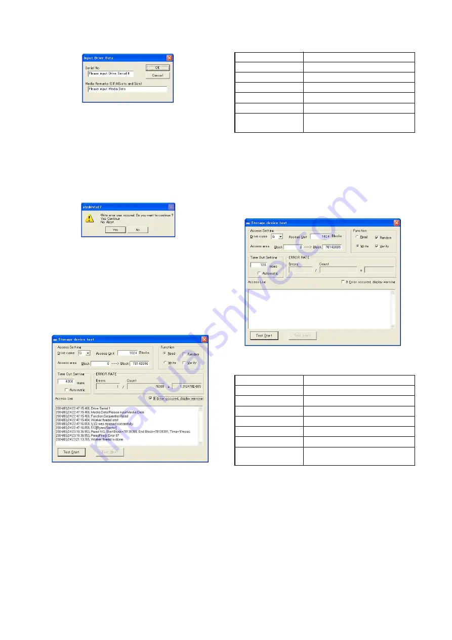
Check that “Input Drive Data” screen is displayed.

Fig. 3-1-19.

8)

Input serial No and media remarks.
For example:
   Hard disk ............................................................ HDD(BIR)

9)

Click “OK” button.

10) “Storage device test” is performed automatically.
11) Before the “Count” of the ERROR RATE window reaches

“76308”, when the “Read error was occurred. Do you want to
continue?” message is displayed, the hard disk drive is
malfunction. Click the “No” button to abort the test.

Fig. 3-1-20.

12) When the "Count" of the ERROR RATE window reaches

"76308", the test is completed.

13) Check that the “Errors” window indicate “1”.

Note:

The “Errors” window (Errors count) will indicate “1” after the
“Count” reaches “76308”, but this is not true error, so it is
considered that the hard disk drive has no error.
When the “Errors” window (Errors count) indicate “2” or more,
the hard disk drive is malfunction.

Fig. 3-1-21.

3-2-7.

Burn In (Write) Check

Mode

USB

Power Supply

AC power adaptor

Test Program

80minAg.exe

MemoryStick

Not necessary

CompactFlash

Not necessary

Microdrive

Not necessary

Specified Value

Hard disk drive:
  Error rate = 5.000000E – 002 or less

Note:

When the hard disk is checked, the data memorized on hard disk
will be erased. After the hard disk check finishes, perform “3. HDD
Self Format” again.

Checking method:
1)

Turn on the power of HDPS-M10.

2)

Connect HDPS-M10 and PC using the USB cable.

3)

Double click “80minAg.exe” of the “Bi(w)” folder, and start
“Storage device test” on the PC.

4)

Check that “Storage device test” screen is displayed.

Fig. 3-1-22.

5)

Set up “Storage device test” as follows.

Drive name (Note)

G

Read

No check

Write

Check

Random

Check

Verify

Check

Time out setting

4000msec

Automatic

No check

If error occurred,

No check

display warning

Note:

The drive letter (e.g., “G:”) differs depending on the PC.

6)

Click “Test Start” button.

Summary of Contents for HDPS-M10 - Data Storage Wallet

Page 1: ...anese Model SERVICE MANUAL HDD PHOTO STORAGE Link Link Revision History Revision History Ver 1 1 2006 10 Sony EMCS Co 2006J1600 1 2006 10 Published by Kohda TEC 9 876 896 12 HDPS M10 HDPS M10 DISASSEMBLY REPAIR PARTS LIST ADJUSTMENTS SPECIFICATIONS DISASSEMBLY REPAIR PARTS LIST ADJUSTMENTS SPECIFICATIONS How to use Acrobat Reader How to use Acrobat Reader Revised 1 ...

Page 2: ...ent conditions Operating temperature 5 C to 40 C 40 F to 104 F temperature gradient less than 10 C hour 50 F hour Operating humidity 20 to 80 non condensing Dimensions Approx 135 30 92 mm 5 3 8 1 3 16 3 5 8 in W H D Mass Approx 300 g 10 6 oz Supplied accessories AC power adapter SONY Model HDAC M1 MCS AC1 1 Carrying case 1 Hand strap 1 Indicator label 1 Operating Instructions this document PhotoDi...

Page 3: ...ry solder Ordinary soldering irons can be used but the iron tip has to be applied to the solder joint for a slightly longer time Soldering irons using a temperature regulator should be set to about 350 C Caution The printed pattern copper foil may peel away if the heated tip is applied for too long so be careful Strong viscosity Unleaded solder is more viscous sticky less prone to flow than ordina...

Page 4: ...3 2 3 Stand Alone Copy Check and Final Function USB Mode Check 3 5 3 2 3 1 Stand Alone Copy Check 3 5 3 2 3 2 Final Function USB Mode Check 3 5 3 2 3 2 1 Preparations 3 5 3 2 3 2 2 Final Function USB Mode Check 3 7 3 2 4 USB 1 1 Confirmation Check 3 8 3 2 5 Final Function 2 USB Mode Check 3 8 3 2 6 Burn In Read Check 3 9 3 2 7 Burn In Write Check 3 10 3 2 8 NTFS format 3 11 3 2 9 HDD Self Format 3...

Page 5: ... 5 Battery plate Battery plate sheet 1 Lift the PWB board out from the top case assembly case 2 Two positioning holes 3 Remove the PWB board in the direction of the arrow 1 3 2 3 2 1 1 3 2 4 1 Connector 2 Flexible flat cable 3 PWB board 1 Tapping screw M2x3 silver 2 Two hooks 3 Peel off the adhesive side of the flexible side 4 LCD set assembly b 3 4 2 1 6 5 a 1 2 5 4 3 Note When installing the PWB...

Page 6: ...NOTE NOTE HDPS M10 Link Link 2 REPAIR PARTS LIST OVERALL SECTION OVERALL SECTION TOP CASE SECTION TOP CASE SECTION EXPLODED VIEWS EXPLODED VIEWS ACCESSORIES ACCESSORIES PWB ASSEMBLY PWB ASSEMBLY ...

Page 7: ...tal Oxide film resistor F nonflammable SEMICONDUCTORS In each case u µ for example uA µA uPA µPA uPB µPB uPC µPC uPD µPD When indicating parts by reference number please include the board name The components identified by mark 0 or dotted line with mark 0 are critical for safety Replace only with part number specified Les composants identifiés par une marque 0 sont critiques pour la sécurité Ne le...

Page 8: ...FLAT 9 4 683 253 01 SCREW PRECISION M3X4 10 7 685 102 14 SCREW P 2X4 TYPE2 NON SLIT 11 A 1134 387 A ABSORBER ASSY SERVICE B 12 A 1133 813 A LID R ASSY 13 7 685 105 14 TAPPING P 2X8 NON SLIT 14 A 1133 811 A BOTTOM CASE ASSY 15 4 682 526 01 RUBBER FOOT 16 2 059 938 01 BOTTOM SHIELD CN201 1 778 652 31 CONNECTOR FFC ZIP 50P HDD 2 1 EXPLODED VIEWS A A C B B D D C E F F E 1 14 10 12 2 10 3 15 15 11 9 8 ...

Page 9: ...4 2 629 870 01 LCD DAMPER 55 A 1133 872 A LCD SET 56 4 671 885 01 SCREW TAPPING SPECIAL 57 2 637 218 01 LCD HOLDER INSULATOR 59 2 637 219 01 LCD FPC TAPE 60 2 629 873 01 POWER BUTTON 61 2 629 871 01 CANCEL BUTTON ns ns ns 52 53 60 59 51 54 55 56 57 61 ns Note Note When the TOP CASE ASSY SERVICE Ref No 52 on this page is going to be replaced with the TOP CASE ASSY SERVICE with suffix B do not insta...

Page 10: ...scription Ref No Part No Description CN6 1 817 171 11 MINI B USB CONNECTOR 5PIN CN7 1 770 160 21 PIN CONNECTOR PC BOARD 2P BATTERY CN8 1 580 055 21 PIN CONNECTOR SMD 2P BACKLIGHT 0F1 1 576 415 11 FUSE MICRO 1608 TYPE 2A 32V S1 1 572 595 11 SWITCH TACTIL REFLOW TYPE COPY CANCEL S2 1 572 595 11 SWITCH TACTIL REFLOW TYPE COPY CANCEL S3 1 771 627 11 SWITCH TACTIL POWER S4 1 762 078 11 SWITCH SLIDE HOL...

Page 11: ...wer cord Main lead 1 AUS NZ model 0 1 555 074 32 Power cord Main lead 1 EU SMAP LA model 0 1 824 910 41 Power cord Main lead 1 US CND model 0 1 757 562 21 Power cord Main lead 1 KR model 0 1 776 985 32 Power cord Main lead 1 CH model 0 1 782 476 22 Power cord Main lead 1 J model 0 1 790 732 32 Power cord Main lead 1 UK HK model 0 1 823 935 51 Power cord Main lead 1 TW model 0 1 830 518 21 AC Power...

Page 12: ...installed and with USB 2 0 port and DVD playback capability USB cable 1 827 038 11 AC power adaptor HDAC M1 Note1 J 5 J 6 J 7 J 8 Memory Stick PRO 256MB CompactFlash Type I 512MB Microdrive 1GB Fig 3 1 1 AC power code Note1 Abbreviation CND Canadian model AUS Australian model CH Chinese model HK Hong Kong model KR Korea model J Japanese model TW Taiwan model NZ New Zealand model SMAP Sony Marketin...

Page 13: ...el Check trf_files 003 FC2_BI r strdevtst7 exe Final Function 2 USB Mode Check Burn In Read Check Matrix for changed parts and operation required for Storager Service Note1 Use trf_file 001 trf_file 002 and trf_file 003 as test file Note2 HDPS folder and ReadMe html file are stored in the HDPS10 Photo Manual DVD ROM Note3 Adjustment and check works should be carried out according to the operation ...

Page 14: ...nal Function USB Mode Check 4 USB 1 1 Confirmation Check 5 Final Function 2 USB Mode Check 6 Burn In Read Check 7 Burn In Write Check 8 NTFS Format 9 HDD Self Format 10 Photo Diary Software Download Fig 3 1 2 CONNECTION OF EQUIPMENT Personal computer with USB 2 0 port DC IN USB USB AC IN AC power adaptor ...

Page 15: ...alone Power Supply AC power adaptor Test Program Not necessary MemoryStick Not necessary CompactFlash Not necessary Microdrive Not necessary Specified Value Nothing Formatting method 1 Disconnect the USB cable 2 Turn on the power of the HDPS M10 3 Check that the following message is displayed on the LCD window If the message of Step 8 is displayed HDD self format has been performed already HDD For...

Page 16: ... COMPLETED 0001 0001 000 000 12 Eject the CompactFlash 13 Insert the micro drive to the CompactFlash micro drive slot 14 Wait until the following message is displayed on the LCD window READY 0001 000 COPY to start 15 Press COPY button to copy files from the micro drive to HDD 16 When the copy is completed the following message is displayed on the LCD window COMPLETED 0001 0001 000 000 17 Eject the...

Page 17: ...003 t 20050505 003 6 Save the Storager seq file 7 Right click the Storager cfg file of the FC1 folder then select Open 8 Choose the Notepad from the list of apprications then click OK 9 The notepad application starts and the edit screen of the Storager cfg file is displayed 10 Change the drive letters as follows G t Drive letter of HDPS M10 s hard disk drive that displayed on your computer system ...

Page 18: ...ch memorize trf_file 001 file CompactFlash CompactFlash which memorize trf_file 002 file Microdrive Microdrive which memorize trf_file 003 file Specified Value Files compare OK should be displayed Checking method 1 Turn on the power of HDPS M10 2 Connect HDPS M10 and PC using the USB cable 3 Double click the FC1 exe of the FC1 folder to start up the program 4 Check that FC1 windows displayed and c...

Page 19: ...tick Blank Memory Stick PRO CompactFlash Blank CompactFlash Microdrive Blank Microdrive Specified Value Memory Stick PRO Error rate 0 000000E 000 CompactFlash Error rate 0 000000E 000 Microdrive Error rate 0 000000E 000 Hard disk drive Error rate 5 000000E 002 or less Note1 When the storage media is checked the data memorized on it will be erased After the check finishes format the storage media a...

Page 20: ... 0 01 0 05 5 Fig 3 1 17 3 2 6 Burn In Read Check Mode USB Power Supply AC power adaptor Test Program strdevtst7 exe MemoryStick Not necessary CompactFlash Not necessary Microdrive Not necessary Specified Value Hard disk drive Errors count 0 Checking method 1 Turn on the power of HDPS M10 2 Connect HDPS M10 and PC using the USB cable 3 Double click strdevtst7 exe of the FC2_BI r folder and start St...

Page 21: ...e 2 or more the hard disk drive is malfunction Fig 3 1 21 3 2 7 Burn In Write Check Mode USB Power Supply AC power adaptor Test Program 80minAg exe MemoryStick Not necessary CompactFlash Not necessary Microdrive Not necessary Specified Value Hard disk drive Error rate 5 000000E 002 or less Note When the hard disk is checked the data memorized on hard disk will be erased After the hard disk check f...

Page 22: ...ormat 3 2 9 HDD Self Format This operation is the same as 3 2 2 HDD Self Format Please refer to 3 2 2 HDD Self Format 3 2 10 Photo Diary Software Download Mode USB Power Supply AC power adaptor Test Program Folder and file in the HDPS10 Photo Manual DVD ROM MemoryStick Not necessary CompactFlash Not necessary Microdrive Not necessary Specified Value About 460MB Download method 1 Turn on the power ...

Page 23: ...o other program interferes with the installation save all work and close all other programs The Taskbar should be clear of applications before proceeding 4 Copy the following firmware file to the desk top of the PC Sony0219_US exe US model Sony0219_WW exe The other model Firmware Upgrade 1 Connect the HDPS M10 and the PC using the USB cable 2 Turn on the power of HDPS M10 Note TheAC power adaptor ...

Page 24: ...PS M10 Wait until the HDPS M10 is detected by the PC The HDPS M10 LCD screen icons may be distorted Run the Firmware upgrade tool again and follow the Firmware Upgrade procedure above The LCD screen will return to normal when the firmware upgrade is successful The figure shown below is an example of how the distorted LCD screen icons may appear Fig 3 1 30 4 The new firmware version is older than s...

Page 25: ...S M10 will be turned off automatically 7 Turn the power of HDPS M10 on and confirm that the language is changed to the selected language 3 2 12 Full Charge Implementation When the firmware is upgraded or when the battery is removed or when the PWB Assy is replaced or when the battery assembly is replaced implement Full Charge of Battery as described below Battery full charge method 1 Battery charg...

Page 26: ...pplied to the Service Manual depending on the date of issue Switching a page To move to the first page click the To move to the last page click the To move to the previous page click the To move to the next page click the Reversing the screens displayed once To reverse the previous screens operation one by one click the To advance the reversed screens operation one by one click the Application to ...

Page 27: ...Revision History 987689612 pdf HDPS M10 Ver 1 0 1 1 Date 2005 08 2006 10 History Official Release Revised 1 Contents Change of repair parts list Change of adjustments S M Rev issued Yes Reverse ...

Reviews: