– 9 –
2-8. DISC TABLE
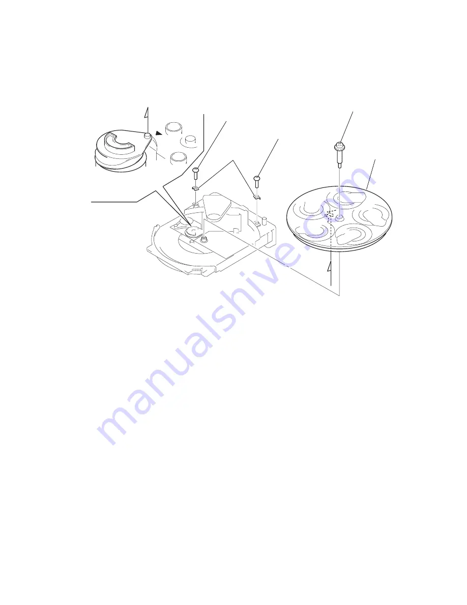
NOTE:
When the disc table is installed, adjust the positions of
roller cam and mark
”
as shown in the figure, then set to
the groove of disc table.
A
A
2
Screw (BVTP3X8)
3
Bracket (BU)
1
Screw (BVTP3X8)
4
Stop screw
5
Disc table


