


66
HCD-WZ8D
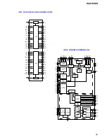
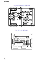
• IC401 M30622MGN-B22FP (AEP, UK, RU, E2, MX) , -B12FP (EXCEPT AEP, UK, RU, E2, MX)(SYSTEM CONTROL)(MAIN BOARD)
Pin No.
1
2
3
4
5
6
7
8
9
10
11
12
13
14
15
16
17
18
19
20
21
22
23
24
25
26
27
28
29
30
31
32
33
34
35
36
37
38
39
40
41
42
43
44
45
46
47
48
49
50
I/O
I
—
—
I
O
I
O
—
—
I
O
I
O
—
I
—
I
I
—
I
O
O
O
I
I
O
O
—
O
O
—
—
O
—
I
O
O
O
O
I
O
I
I
O
O
I
O
O
O
Oº
Pin Name
MIC-CHECK
NO USE
NO USE
SIRCS
DSP DIN
DSP DOUT
DSP CLK
BYTE
CN VSS
XC-IN
XC-OUT
RESET
X-OUT
VSS
X-IN
VCC
NMI
RDS INT
NO USE
AC-CUT
DSP XRST
DSP HCE
DSP BST
DSP ACK
DSP ERROR
DSP EXLOCK
DSP PM
DSP DECODE
IIC-CLK
IIC-DATA
NO USE
NO USE
A-MUTE
SOFT-TEST
MUTE REQ
IF-VIDEO MUTE2
IF-VIDEO MUTE1
IF-DVD-RESET
IF-DVD-POWER
RDS-DATA
ST-MUTE
STEREO
TUNED
ST-CE
ST-DOUT
ST-DIN
ST-CLK
SW MUTE
VR-CLK
VR-DATA
Description
Microphone detection signal input
Not used
Not used (connected to the ground)
SIRCS signal input fromthe remote sensor (IC601)
Serial data output to the DSP (IC601)
Serial data input from the DSP (IC601)
Serial clock output to the DSP (IC601)
External data bus width selection terminal
Processor modes switch terminal
Sub clock input terminal (32.768kHz)
Sub clock output terminal (32.768kHz)
System reset signal input
Main system clock output terminal (16MHz)
Ground terminal
Main system clock input terminal (16MHz)
Power supply terminal (+3.3V)
NMI input terminal (fixed at “H”)
RDS INT signal input
Not used (connected to the ground)
AC cut detection signal input
Reset signal output to the DSP (IC601)(“L” : reset)
Chip select signal output to the DSP (IC601)
Boot strap signal output to the DSP (IC601)
Acknowledge signal input from the DSP (IC601)
ERROR signal input from the DSP (IC601)
PLL lock error and data error flag signal output to the DSP (IC601)
PLL reset signal output to the DSP (IC601)
Not used
IIC serial clock output
IIC serial data output
Not used (connected to the ground)
Not used (connected to the ground)
Audio muting signal output
Soft test teminal
Audio muting request signal input from the DVD system processor (IC207)
Video muting signal output
Video muting signal output
System reset signal output to the DVD system processor (IC207)
DVD power supply control signal output (“H” : on, “L” : off)
RDS data input
Muting signal output to the tuner
Stereo detection signal input from the tuner (“L” : in, “H” : off)
Tuner tuned status signal input from the tuner (“L” : in, “H” : off)
Tuner chip enable signal output to the tuner
Data output to the tuner
Data input from the tuner
Clock output to the tuner
Sub woofer muting signal output
Clock output to the audio signal processor (IC301)
Data output to the audio signal processor (IC301)