4
SECTION 1
SERVICING NOTE
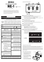
ADJUSTMENT OF CAM PHASE
Absorber
Absorber
SW lever
SW lever
Boss
Cam
Slider (3)
Screw
(BVTP2.6x8)
Screw
(PTTWH2.6x8)
Screw
(BVTP2.6x8)
Groove of slider (3)
Hole of slider (3)
Guide (L)
Boss (Four point)
Guide (R)
Slider (2)
Lever (1)
Lever (1)
Mecha cover
Cam
Boss
Boss
Boss
Cam
Boss
Insert the cam so that the boss touches the SW lever
at the left shown in the figure.
Rotate the cam in the arrow direction, and adjust the
phase until the boss touches the SW lever shown in
the figure.
With the phase adjusted, attach the parts using the following procedure.
STEP1
Insert the boss of the slider (3) in the groove of
the cam.
STEP2
Set the mecha cover to the groove
on the slider (3) and attach.
STEP3
Insert the boss of the lever (1) in the hole of the
slider (3) and attach.
STEP4
While bending the slider (2) slightly in the arrow
direction, insert it in the groove of the guides (L)
and (R) and attach.
Summary of Contents for HCD-EX1
Page 8: ...8 This section is extracted from instruction manual ...
Page 17: ...HCD EX1 17 17 ...
Page 23: ...HCD EX1 23 23 5 9 SCHEMATIC DIAGRAM AMP SECTION Page 20 Page 29 Page 29 ...
Page 25: ...HCD EX1 25 25 5 11 SCHEMATIC DIAGRAM PANEL SECTION Page 19 ...
Page 27: ...HCD EX1 27 27 5 13 SCHEMATIC DIAGRAM POWER SECTION Page 29 ...
Page 29: ...HCD EX1 29 29 5 15 SCHEMATIC DIAGRAM REG SECTION Page 27 Page 23 Page 20 ...