DCR-HC90/HC90E
2-1
2-2
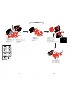
2-1. DISASSEMBLY
The following flow chart shows the disassembly procedure.
2. DISASSEMBLY
Note:
Be very careful not to
damage the flexible board.
1
Two screws (M1.7x4) silver
2
FP-069 flexible board
3
Control switch block (EZ11600)
4
Screw (M1.7x4) silver
5
Two screws (M1.7x4) silver
6
Screw (M1.7x4) silver
7
FP-066 flexible board (30P)
8
FP-063 flexible board (16P)
9
Cabinet (R) sction
1
Open the LCD panel.
2
Screw (M1.7x5) silver
3
Screw (M1.7x4) silver
4
Screw (M1.7x4) silver
5
FP-056 flexible board (20P)
6
Front panel section
HELP 01
Screw
M1.7x4
3-989-735-31
Screw
M1.7x5
3-083-261-01
Screw
M1.7x2.5
3-989-735-01
A
Screw
M1.7x4
3-078-893-21
G
C
B
5
2
1
5
4
6
3
1
2
1
Two screws (M1.7x4) silver
2
LCD section
2
1
5
4
9
3
7
8
1
Two screws (M1.7x4) silver
2
Screw (M1.7x4) silver
3
Screw (M1.7x5) silver
4
P cabinet (C)
5
Tape (A)
6
FP-066 flexible board
7
Hinge section
8
Control key block (SB9000) (6P)
9
Three screws (M1.7x2.5) silver
q;
P frame, PD-240 board, SP base adhesive sheet,
TP block assembly, Speaker base ,
Light guide plate block, Piezoelectric buzzer
qa
Panel cushion, P cabinet (M)
6
1
3
5
6
4
2
1
Screw (M1.7x2.5) silver
2
Two claws
3
Two claws
4
Hinge cover (C)
5
Remove the switch
(S001)
from the
groove.
6
Hinge cover (M)
7
Hinge assembly, FP-066 flexible board
7
B
A
A
A
A
B
C
A
C
Shorting jig
(1k
Ω
/ 1w)
Capacitor
CL8404
(check land of discharge)
ST-114
board
MD frame
Discharging the capacitor.
Caution
Screw
M1.4x1.5
3-062-214-01
Tapping screw
M1.7x3.5
3-078-890-01
F
D
Tapping screw
M1.7x4
3-080-204-11
E
Silver
Black
1
9
7
8
6
5
3
2
A
A
A
4
A
1
Open the cabinet (G) assembly.
2
Two screws (M1.7x4) silver
3
Screw (M1.7x2.5) silver
4
Cabinet top
5
Two screws (M1.7x2.5) silver
6
Screw (M1.7x4) silver
2
1
3
4
5
6
C
C
A
A
3
6
4
1
2
C
1
Two screws (M1.7x2.5) silver
2
FP-064 flexible board (12P)
3
FP-067 flexible board (14P)
4
FP-059 flexible board (CK-145 board)(20P)
5
Claw
6
Remove the cabinet (upper) block assembly
in the direction of the arrow.
1
2
3
4
1
Screw (M1.7x2.5) silver
2
FP-070 flexible board (16P)
3
Flash unit (18P)
4
ST-114 board
C
See page 2-3
1
Peel off the tape (A)
2
Screw (M1.7x2.5) silver
3
The hook portion of LD-176 board.
4
FP-057 flexible board (39P)
5
Two screws (M1.7x2.5) silver
6
FP-058 flexible board (80P)
7
Lens section
1
6
2
5
7
4
3
C
C
qa
q;
Summary of Contents for Handycam DCR-HC90
Page 2: ... 2 DCR HC90 HC90E SPECIFICATIONS ENGLISH JAPANESE ENGLISH JAPANESE ...
Page 3: ... 3 DCR HC90 HC90E ENGLISH JAPANESE ENGLISH JAPANESE ...
Page 5: ... 5 DCR HC90 HC90E ENGLISH JAPANESE ENGLISH JAPANESE ...
Page 13: ...1 6 DCR HC90 HC90E SECTION 1 SERVICE NOTE ENGLISH JAPANESE ENGLISH JAPANESE ...
Page 14: ...1 7 DCR HC90 HC90E ENGLISH JAPANESE ENGLISH JAPANESE ...
Page 15: ...1 8 DCR HC90 HC90E ENGLISH JAPANESE ENGLISH JAPANESE ...
Page 16: ...1 9 DCR HC90 HC90E ENGLISH JAPANESE ENGLISH JAPANESE ...
Page 17: ...1 10E DCR HC90 HC90E ENGLISH JAPANESE ENGLISH JAPANESE ...
Page 68: ...5 14 5 REPAIR PARTS LIST 5 REPAIR PARTS LIST DCR HC90 HC90E J MODEL ...

