background image

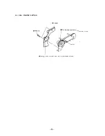
2-5. DIAL POINTER SETTING

 R 

the direction of arrow.

 tuning capacitor drum fully 

to the direction of arrow.

Summary of Contents for FDT-5BX5

Page 1: ...ono jack 7 5 dBs input impedance more than 47 kilohms E A R P H O N E e a r p h o n e jack impedance 8 300 ohms 13 5V DC See Power sources page 4 Power consumption 20W 135V 1 48A AC adaptor use Dimensions Approx 165 x 211 x 224 mm w h d 6 l 2x 8 3 s x 8 y a inches incl projecting parts M a s s Approx 2 7kg 5 lb 15 oz Supplied accessory AC power adaptor ACE55 1 Design and specifications are subject...

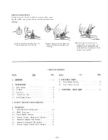
Page 2: ...up the rubber cap and pulling up it in the direction of the arrow 0 TABLEOFCONTENTS Section J it Section Title 1 GENERAL 2 DISASSEMBLY 2 1 Rear Cabinet 2 2 D Board 2 3 Dial Assy 2 4 Cathode ray Tube 2 5 Dial Pointer Setting 3 SAFETY RELATED ADJUSTMENTS 9 4 6 6 7 7 8 5 EXPLODED VIEWS 5 1 Rear Cabinet Section 5 2 Front Cabinet Section 6 ELECTRICAL PARTS LIST 4 DIAGRAMS 4 1 Semiconductor Lead Layouts...

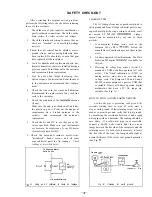
Page 3: ...elow To Exposed Metal Parts on Set 0 15rF A C wltmerer 10 75 vj It Earth Ground ig A Using an AC voltmeter to check AC leakage LEAKAGE TEST The AC leakage from any exposed metal part to earth ground and from all exposed metal parts to any exposed metal part having a return to chassis must not exceed 0 5 mA 500 microampers Leakage current can be measured by any one of three methods 1 A commercial l...

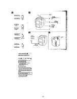
Page 4: ...ct se EAC 60 antenna cable 1 supplied lo F typs plug o CCDdM antenna cable not supplied for F type jack To mnnect CCD4M m Die F type plug use EAC 40 F type joint not supplied II you need to prepare the end of the antenna cable us EAC 33 antenna co eclOr not supplied Power Sources Use the supplied AC power adapton Note Use only Ihe svppliod AC powor ada to Da not se any olhe AC power adaptw q 1 3 6...

Page 5: ...0 CONTR n 9 COLOR n Q H U E 1 I I Aurilar 0 ruminissado L to EARPHONE a EARPHONE Listening to the Radio H 5 ...

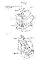
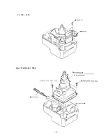
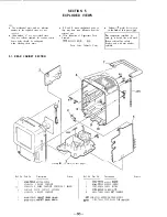
Page 6: ...SECTION 2 DISASSEMBLY Note Follow the disassembly procedure in the numerical order given 2 1 REAR CABINET P BVTP3X12 2 2 D B O A R D 6 ...

Page 7: ...2 3 DIAL ASSY d BVTP3X12 24 CATHODE RAY TUBE tapping screw washer hea d Q cathode ray tube When removing take care of catch by the band knobs j band knoha ...

Page 8: ...2 5 DIAL POINTER SETTING R board the direction of arrow Turn th tuning capacitor drum fully to the direction of arrow 8 ...

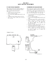
Page 9: ...Q506 R575 C365 R361 R360 1 Turn the POWER switch ON and supply 13 5 0 5V DC to the DC IN jack 2 Receive the monoscope signals 3 Set the PICTURE and BRIGHTNESS control to center position 4 Confirm the voltage of TP512 is within 5 22 0 5V DC 5 Supply DC voltage from the regulated dc power supply to TP512 and gradually increase the voltage towards 6 23V then confirm the hold down raster will disappea...

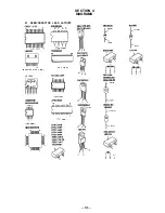
Page 10: ...V I E W M A R K I N G S I D E V I E W LA7830 TC74HC123F 19 9 I a RD33ES 62 RD6 2ES B2 cathode 2SC2555 2 TOP VIEW pPC1394C b 4 anode RD15F B3 lN4002 CATHODE LM2904M MC34063AM B E 2SC2688 LK r side 1795 I234 ANODE I 7 ITOP VIEW TOP VIEW DTA124XK DTA144EK DTC114EK DTC124XK DTC144EK 2SA1162 G 2SC2712 YG 2SC2714 Y 2SC2958 L MN73203SFB 2SK705 RD8 2M 82 lSS153 3 Gi A 2 L 7 N C 0 2 3 I d b lO ...

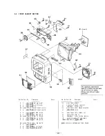
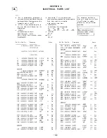
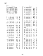
Page 11: ...Cabinet s Color The components identified by mark A or dotted line with mark A are critical for safety Replace only with part number specified including n C board on next page Ref No Part No Description Remark 1 4 041 783 01 BUTTON POWER 2 A 3016 485 A F BOARD COMPLETE 3 A 3016 483 A D BOARD COMPLETE INCLUDING C BOARD 4 4 041 781 01 PLATE CONTACT ANTENNA 5 A 3016 482 A A BOARD COMPLETE Ref No Part...

Page 12: ...TTON CH WHITE 5 6 4 041 779 01 KNOB TUNE BLACK 56 4 041 779 11 KNOB TUNE WHITE 5 7 4 041 774 01 POINTER 5 8 4 041 778 01 KNOB VOL BLACK 5 8 4 041 778 11 KNOB VOL WHITE Remark Ref No Part No Description Remark 5 9 4 041 785 01 BRACKET 6 0 A 3016 486 A R BOARD COMPLETE 6 1 3 714 118 01 SCREW 1 7X4 6 2 4 041 787 01 DRUM TUNING CAPACITOR 6 3 4 041 773 01 FILTER 6 4 4 041 789 01 PLATE GROUND CRT 6 5 4 ...

Page 13: ...d line with mark Some delay should be anticipated A are critical for safety when ordering these items Replace only with part number l SEMICONDUCTORS specified In each case u b for example uA uPA JJPA uPB uPB UPC uPC uPD LLPD l CAPACITORS uF JF 0 COILS uH bH Remark Ref No Part No Description Cl76 l 163 031 11 CERAMIC CHIP Cl79 l 127 481 00 ELECT SOLID C181 183 l 163 031 11 CERAMIC CHIP C201 206 l 1...

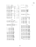
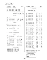
Page 14: ...719 400 18 DIODE MA152WK D307 B 719 106 35 DIODE RDB 2M B2 D345 B 719 400 18 DIODE t 41521 D380 B 719 800 76 DIODE lSS226 D401 8 719 800 76 DIODE lSS226 D403 B 719 400 18 DIODE MA152WK Ref No Part No Description DELAY LINE DL301 l 406 920 11 DELAY LINE IC IClOl B 759 192 70 IC MN73203SFB IC102 8 759 981 69 IC LMZ904M IC103 B 759 206 28 IC TC74HC123F IC301 8 759 194 21 IC TA8864AN JACK JlOl 1 563 8...

Page 15: ...ow 2 2K 5 l lOW 22K 5 l lOW 2 2K 5 l low 47K 5 l low 1K 5 l low Ref No Part No Description R143 l 216 022 00 METAL CHIP R150 l 216 073 00 METAL CHIP R151 l 216 073 00 METAL CHIP R153 l 216 073 00 METAL CHIP R154 l 216 073 00 METAL CHIP R160 l 216 081 00 METAL CHIP R161 l 216 077 00 METAL CHIP R162 l 216 069 00 METAL CHIP R163 l 216 085 00 METAL CHIP R164 l 216 079 00 METAL CHIP R165 l 216 085 00 M...

Page 16: ...6 908 11 RESISTOR NElWORK CHIP TYPE lOKK4 VARIABLE RESISTOR RVlOl l 238 602 11 RES ADJ CARBON 47K RV102 l 238 600 11 RES ADJ CARBON 10K RV201 l 238 600 11 RES ADJ CARBON 10K RV301 1 223 526 21 RES VAR CARBON 10K HUE RV302 1 223 526 21 RES VAR CARBON 10K COLOR RV303 1 223 526 21 RES VAR CARBON 10K CONTR RV304 1 223 526 21 RES VAR CARBON 10K BRT RV306 l 238 600 11 RES ADJ CARBON 10K RV401 1 223 527 ...

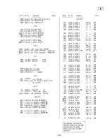
Page 17: ...C508 c509 c510 lx11 C512 c513 c515 C516 c517 C518 c519 C520 c551 C552 c553 c554 AC555 AC556 c557 1 101 005 00 CERAMIC l 126 105 11 ELECT l 129 746 00 FILM l 136 104 00 FILM l 107 636 91 ELECT c570 AC571 C602 l 130 495 00 MYLER l 124 443 00 ELECT l 101 880 00 CERAMIC 1 124 478 11 ELECT 1 124 557 11 ELECT l 130 495 00 MYLAR 1 124 557 11 ELECT 1 124 478 11 ELECT l 130 487 00 MYLAR l 130 499 00 MYLAR ...

Page 18: ... 1 249 412 11 CARBON 3 9 0 5 114w R406 R407 R408 R501 R502 R503 R504 R505 R506 R507 R508 R509 R510 R511 R512 R513 R514 R515 R516 R518 R519 R520 R521 R551 R552 R553 R555 R556 R559 R560 R561 AR562 AR563 R570 R571 R572 AR573 AR574 R575 R576 R577 Part No Description RESISTOR l 249 402 11 CARBON l 249 402 11 CARBON l 249 409 11 CARBON 1 249 417 11 CARBON 1 249 431 11 CARBON 1 249 417 11 CARBON 1 249 44...

Page 19: ...05 8 719 904 02 DIODE lN4002 FUSE AF604 1 532 775 11 FUSE MICRO SECONDARY 8OOmA 125V 1 Ref No Part No Description COIL FB601 603 l 410 396 41 INDUCTOR 0 45uH IC IC601 8 759 100 75 IC UPC1394C AIC602 E 759 054 08 IC MC34063AM COIL 1601 l 407 365 00 COIL CHOKE 1602 l 403 640 11 COIL CHOKE 27uH 1603 l 406 948 11 COIL CHOKE 330uH 1604 l 406 948 11 COIL CHOKE 330uH TRANSISTOR QSOl 8 729 119 78 TRANSIST...

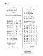
Page 20: ... 10 5ov 5 5ov CONNECTOR CN103 l 564 707 11 PIN CONNECTOk SMALL TYPE 5P VARIABLE CAPACITOR Remark Ref No Part No Description FILTER FL12 1 236 711 21 FILTER BAND PASS IC IC12 B 752 061 79 IC CX20111 T6 COIL 1 1 2 1 422 317 31 COIL AIR CORE L13 1 422 316 11 COIL VHF 1 1 4 l 406 087 11 COIL OSC A 115 l 501 634 11 ANTENNA FEtiITE ROD Am TRANSISTOR Qll E 729 900 53 TRANSISTOR DTC114EK 812 B 729 230 49 ...

Page 21: ...1 79 HEAD WASHER TAPPING SCREW 7 626 323 61 SPRING PIN 4X20 7 682 549 04 SCREW B 3X10 7 685 646 79 SCREW BVTP 3X8 TYPE2 N S 7 685 648 79 SCREW BVTP 3X12 TYPE2 N S 7 685 903 21 SCREW PTPWH 3X8 TYPE2 7 685 546 14 SCREW BTP 3X8 TYF E2 N S The components identified by mark A or dotted line with mark A are critical for safety Replace only with part number specified 9 959 164 11 English 93JO440 1 Printe...

Reviews: