


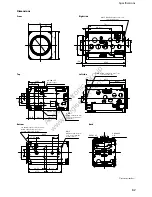
Specifications
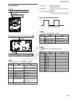
FCB-EH6500(GB) A-EEP-100-11(1)
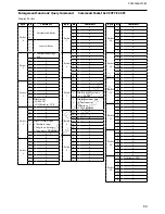
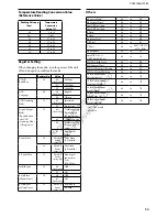
CN200
KYOCERA ELCO Co. 08622201
Pin No.
Name
Level
1
GND
2
Digital Out 0
0 - 3.3 Vp-p
3
Digital Out 1
0 - 3.3 Vp-p
4
Digital Out 2
0 - 3.3 Vp-p
5
Digital Out 3
0 - 3.3 Vp-p
6
Digital Out 4
0 - 3.3 Vp-p
7
Digital Out 5
0 - 3.3 Vp-p
8
Digital Out 6
0 - 3.3 Vp-p
9
Digital Out 7
0 - 3.3 Vp-p
10
GND
11
CLOCK
0 - 3.3 Vp-p
12
GND
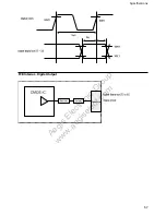
(Precaution when using digital output)
Image noise may occur when using digital output.
Take measures against the noise such as shielding FFC to be
connected and attaching a ferrite core or an electromagnetic
suppression sheet to FFC as needed. The recommended maximum
FFC length is 100 mm or less. Also, firmly ground and connect the
frame so as not to cause the ground potential difference with the
connection destination. Noise may occur due to the ground
potential difference.
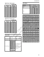
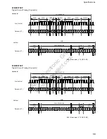
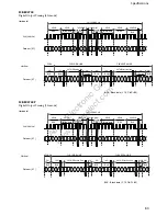
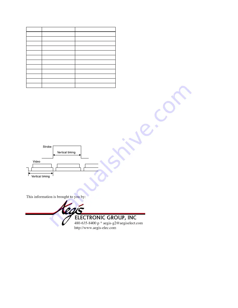
Strobe signal specifications
Aegis
Electronic
Group
www.aegiselect.com