53
Location and Functions of Parts and Controls
Ov
e
rv
ie
w
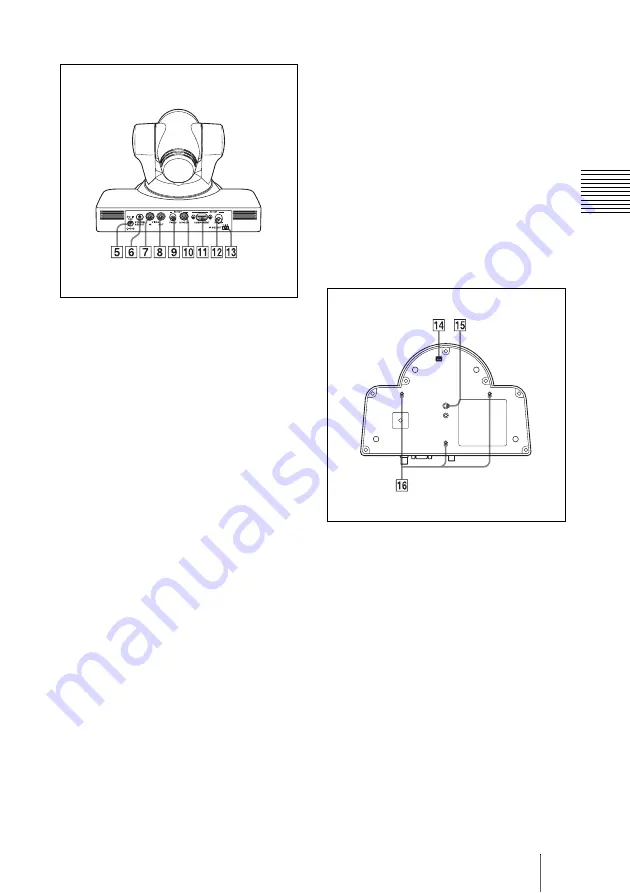
Rear
E
DC IN 12V connector
Connect the supplied AC power adaptor.
F
SYSTEM SELECT switch
Used for selecting the video format of
the signal to be output from the HD OUT
COMPONENT, HD OUT HD-SDI, SD
OUT VIDEO and SD OUT S VIDEO
connectors.
For details, see “Setting of the SYSTEM
SELECT switch” (page 53).
G
VISCA IN connector
Connect to a computer via an RS-232C
interface. When you connect multiple
cameras, connect it to the VISCA OUT
connector of the previous camera in the
daisy chain connection.
H
VISCA OUT connector
When you connect multiple cameras,
connect it to the VISCA IN connector of
the next camera in the daisy chain
connection
I
SD OUT VIDEO connector
Supplies the images as analog composite
signal.
J
SD OUT S VIDEO connector
Supplies the images as analog S video
signals.
K
HD OUT COMPONENT connector
Supplies the images as an analog
component (YPbPr) signal.
L
HD OUT HD-SDI connector
Supplies the images as an HD-SDI
signal which conforms to the
SMPTE292M serial digital interface
standard.
M
IR SELECT switch
Select the camera number when you
operate multiple cameras with the same
Remote Commander.
Bottom
N
BOTTOM switches
Used for baud rate selection and turning
the remote control signal output on/off.
For details, see “Setting of the
BOTTOM switches” (page 54).
O
Tripod screw holes (1/4-20UNC)
When you install the camera to a tripod,
secure the tripod to these screw holes.
P
Fixing screw holes (M3)
Used for fixing the camera to a fitting
using M3 screws.
Setting of the SYSTEM SELECT
switch
This switch allows you to select the video
format of the signal to be output from the
HD OUT COMPONENT, HD OUT HD-
Summary of Contents for EVI-HD1
Page 36: ...36 メニューの構成 メニューの構成 本機のメニューは次のように構成され ています 詳しい内容は 内のペー ジをご覧ください 各項目の初期設定値は 太字で示して います 19 ページ ...
Page 38: ...38 メニューの構成 24 ページ ...
Page 43: ...43 仕様 付録 寸法図 上面 背面 底面 正面 側面 深さ 3 から 5 深さ 5 から 7 深さ 5 以下 単位 mm ...
Page 78: ...78 Menu Configuration See page 64 ...
Page 84: ...Sony Corporation ...


