


7-3
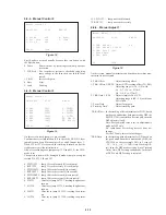
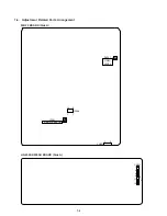
4. Checking Component Video Output R-Y
(MB-78 board)
<Purpose>
This checks component video output R-Y. If it is incorrect, cor-
rect colors will not be displayed when connected to, for instance,
projector.
Mode
CXD1914 (ENC) check in test mode
menu “0” Syscon Diagnosis
Signal
Color bars
Test point
CN251
8
pin (terminating 75
Ω
)
Instrument
Oscilloscope
Specification
700 ± 30 mVp-p
Checking method:
1) Confirm that the R-Y level is 700 ± 30 mVp-p.
Figure 7-5
5. Checking Component Video Output Y
(MB-78 board)
<Purpose>
This checks component video output Y. If it is incorrect, correct
brightness will not be attained when connected to, for instance,
projector.
Mode
CXD1914 (ENC) check in test mode
menu “0” Syscon Diagnosis
Signal
Color bars
Test point
CN251
6
pin (terminating 75
Ω
)
Instrument
Oscilloscope
Specification
1 ± 0.05 Vp-p
Checking method:
1) Confirm that the Y level is 1 ± 0.05 Vp-p.
Figure 7-6
+0
–1.5
+0
–1.5
286 ± 20 mVp-p
11
12
100
µ
F
75
Ω
±
1%
100k
±
1%
CN252
+
Digital voltmeter
11
12
100
µ
F
75
Ω
±
1%
100k
±
1%
CN252
+
Oscilloscope
700 ± 30 mVp-p
(NTSC)
(PAL)
(PAL)
1 ± 0.05 Vp-p
(NTSC)
Summary of Contents for DVP-S500D
Page 12: ...1 2 ...
Page 13: ...1 3 ...
Page 14: ...1 4 ...
Page 15: ...1 5 ...
Page 16: ...1 6 ...
Page 17: ...1 7 ...
Page 18: ...1 8 ...
Page 19: ...1 9 ...
Page 20: ...1 10 ...
Page 21: ...1 11 ...
Page 22: ...1 12 1 12 E ...
Page 52: ...7 5 E 1 2 10 12 14 24 25 CN252 MB 78 BOARD Side B ...