


2-1
Note:
Follow the disassembly procedure in the numerical order given.
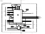
2-2. DISK BASE ASSEBLY REMOVAL
2-4. BU HOLDER REMOVAL
2-3. BASE UNIT REMOVAL
SECTION 2
DISASSEMBLY
DVP-PQ1
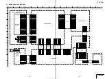
2-1. LID ASSEMBLY REMOVAL
1
Screw
(M1.7
×
4)
3
Screw
(M1.7
×
4)
7
Lid assembly
2
Fulcrum retainer (L)
4
Fulcrum retainer (R)
6
5
2
Four ornamental
screws (M3
×
12)
Four ornamental sheets (screw)
3
Disk base assembly
Note: When you tighten four screws, in order not to make a crevice
between a disk base and a lower case, please hold from both
sides.
3
Two screws
(+BV3
×
10)
5
Two screws
(+BV3
×
10)
8
BU holder
1
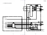
Flexible flat cable
(FIS-003)
(CN811)
2
Connector
(CN950)
7
Two screws
(+BV3
×
10)
6
Four screws
(+BV3
×
10)
4
SW panel assembly
1
Three INS screws
2
Base unit
3
Two flexible flat cables
(FMP-004, 005)
www. xiaoyu163. com
QQ 376315150
9
9
2
8
9
4
2
9
8
TEL 13942296513
9
9
2
8
9
4
2
9
8
0
5
1
5
1
3
6
7
3
Q
Q
TEL 13942296513 QQ 376315150 892498299
TEL 13942296513 QQ 376315150 892498299