


7-2
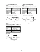
2. Checking Progressive Video Output Level
<Purpose>
This checks whether progressive video output. If it is incorrect,
correct brightness will not be attained when connected to, for in-
stance, projector.
Mode
Play
Signal
Check the Color-bar (100%) signal
on DVD reference disc
Measurement Point
COMPONENT VIDEO OUT (Y)
connector (75
Ω
terminated)
Measuring Instrument
Oscilloscope
Specification
1.00
Vp-p
Checking method:
1) Confirm that the Progressive video output 1.00
Vp-p
Figure 7-2
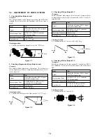
7-2. ADJUSTMENT OF VIDEO SYSTEM
1. Checking Video Output Level
<Purpose>
This checks whether Video Output level satisfy the NTSC/PAL
standard. If it is not correct, the brightness will be too large or
small.
Mode
Play
Signal
Check the Color-bar (100%) signal
on DVD reference disc
Measurement Point
LINE OUT (VIDEO) connector
(75
Ω
terminated)
Measuring Instrument
Oscilloscope
Specification
1.00 Vp-p
Checking method:
1) Confirm that the Video Output level is 1.00 Vp-p.
Figure 7-1
3. Checking S Video Output S-Y
<Purpose>
Check S-terminal video output. If it is incorrect, pictures will not
be displayed correctly in spite of connection to the TV with a S-
terminal cable.
Mode
Play
Signal
Check the Color-bar (100%) signal
on DVD reference disc
Measurement Point
S VIDEO OUT (S-Y) connector
(75
Ω
terminated)
Measuring Instrument
Oscilloscope
Specification
1.00
±
0.05 Vp-p
Checking method:
1) Confirm that the S-Y level is 1.00
±
0.05 Vp-p.
Figure 7-3
4. Checking S Video Output S-C
<Purpose>
This checks whether the S video output S-C satisfies the NTSC/
PAL Standard. If it is not correct, the colors will be too dark or
light.
Mode
Play
Signal
Check the Color-bar (100%) signal
on DVD reference disc
Measurement Point
S VIDEO OUT (S-C) connector
(75
Ω
terminated)
Measuring Instrument
Oscilloscope
Specification
A = 286
±
30 mVp-p (NTSC)
A = 300
±
100 mVp-p (PAL)
Checking method:
1) Confirm that the S-C burst is “A”.
Figure 7-4
+0.04
–0.02
+ 0.04
– 0.02
1.00 Vp-p
+0.04
–0.02
+ 0.04
– 0.02
+ 0.04
– 0.02
1.00
Vp-p
+ 0.04
– 0.02
1.00
±
0.05 Vp-p
A
Summary of Contents for DVP-NS777P
Page 22: ...1 18 E MEMO ...
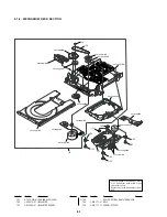
Page 28: ...2 6 2 8 INTERNAL VIEWS TOP VIEW MS 203 MOUNT Optical Device KHM 310BAA BOTTOMVIEW ...
Page 30: ...2 8 E MEMO ...
Page 69: ...6 12 E MEMO ...
Page 73: ...7 4 E MEMO ...


