6-7
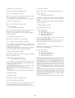
(9-9) Audio Mute Line
ROM audio data
→
ARP (IC806)
→
AV Decoder (IC203)
→
Ana-
log audio output (Mute)
Error 10: ARP (IC806)
→
AV Decoder (IC203) data transfer
error
35: 2ch DAC (IC215) serial transfer interruption is not de-
tected
37: PLL DAC (IC209) serial transfer interruption is not de-
tected
MPEG-audio bit stream data stored in ROM (IC803) are trans-
ferred to the AV Decoder (IC203) via ARP (IC806), and analog
audio data are output from 2ch DAC (IC215).
In such a case, first the mute by I/O of SH (IC805), then the mute
by setting AV Decoder (IC203), and by setting DAC are turned on
respectively to output low frequency tones.
Finally, the mute is turned off to output high frequency tones.
Checking is finished when high frequency tones are heard.
Low tones will be heard before this checking finished, if the mute
is not effective.
To make sure which mute is not effective, the check should be
repeated while paying attention to the message.
If no error is found, the message is displayed to prompt for key
entry.
(9-10) MGA (IC101) 16
→
24 Bit Conversion
ROM audio data
→
ARP (IC806)
→
AV Decoder (16 bit output)
→
MGA (IC101)
→
Analog audio output
Error 10: ARP (IC806)
→
AV Decoder (IC203) data transfer
error
35: 2ch DAC (IC215) serial transfer interruption is not de-
tected
37: PLL DAC (IC209) serial transfer interruption is not de-
tected
Audio output data from AV Decoder (IC203) are set to 16 bit data,
then they are checked if the clock delay is applied by turning on
the select switch. To make sure, they are outputagain by turning
off the select switch. If normal, the tones in the first check are
same as in “MPEG Audio Analog Output”, but the sound level in
the second check will be very lowered (about – 48dB).
If no error is found, the message is displayed to prompt for key
entry.
(9-11) MGA DCS Select Switch Check
ROM audio data
→
ARP (IC806)
→
AV Decoder (IC203)
→
MGA
→
Analog audio output
Error 10: ARP (IC806)
→
AV Decoder (IC203) data transfer
error
35: 2ch DAC (IC215) serial transfer interruption is not de-
tected
37: PLL DAC (IC209) serial transfer interruption is not de-
tected
This diagnosis checks if the signals from AV Decoder (IC203) to
DAC are shut off by turning on the DCS select switch.
First, low frequency tones are output by turning on the DCS select
switch, then to make sure, high frequency tones are output by turn-
ing off the DCS select switch.
The check is finished if high frequency tones are heard.
The DCS switching is not effective when low frequency tones are
heard before the check is finished.
If no error is found, the message is displayed to prompt for key
entry.
(10) AC-3 Concerned
(10-2) AC-3 DSP Register
Serial register write
→
Register read matching check
Error 05: Write/read data mismatch error
11: Serial receiving error
55: AC-3 Decoder (IC104) serial transmit interruption is not
detected
20 bit data are written to the address 02F61h of AC-3 Decoder
(IC104), and they are read to check for matching.
Checking is made 20 times by shifting 1 bit each to the right of the
data from 0x00001 to 0x80000.
(10-3) AC-3 DSP Reset Line
Serial register write
→
Hard reset
→
Register read
Error 02: Reset error
11: Serial receiving error
55: AC-3 Decoder (IC104) serial transmit interruption is not
detected
20 bit data 0x34567 is written to the address 02F61h of AC-3 De-
coder (IC104), and the hardware is reset. Then, the data is read to
check if it is initialized to 0x00000.
Summary of Contents for DVP-C600D - 5 Disc Cd/dvd Player
Page 10: ...1 1 SECTION 1 GENERAL This section is extracted from US model instruction manual DVP C600D ...
Page 11: ...1 2 ...
Page 12: ...1 3 ...
Page 13: ...1 4 ...
Page 14: ...1 5 ...
Page 15: ...1 6 ...
Page 16: ...1 7 ...
Page 17: ...1 8 ...
Page 18: ...1 9 ...
Page 19: ...1 10 ...
Page 20: ...1 11 ...
Page 21: ...1 12 ...
Page 22: ...1 13 1 13 E ...
Page 37: ...DVP C600D 4 3 4 4 FRAME 2 2 FRAME SCHEMATIC DIAGRAM 2 2 ...

