background image

70

Menu Contents

C

h

ap
te

r 4


 M
e

nu 

S

e

tti

n

gs

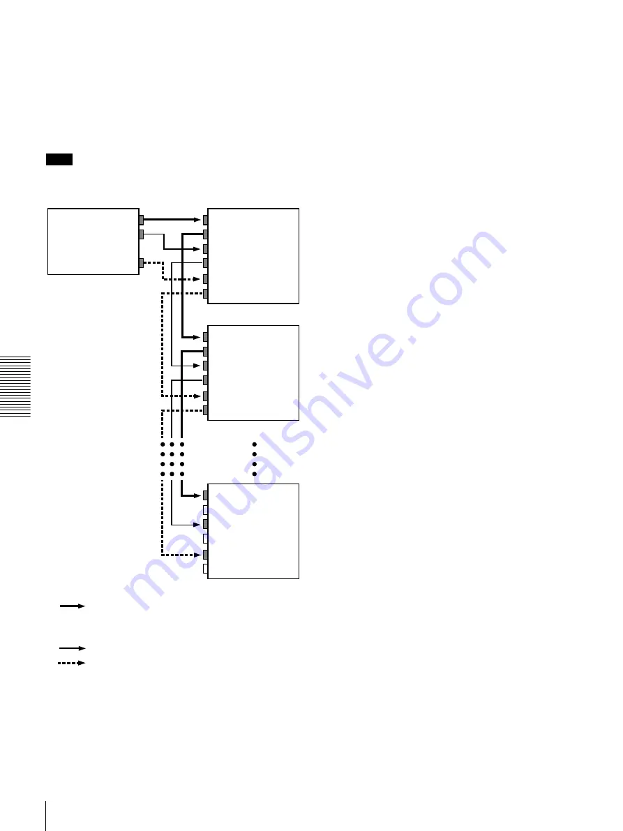
VIDEO OUTPUT PHASE mode

The time code output signal is synchronized with the 
output video signal.
This mode is appropriate when outputting signals from a 
single device to a number of VCRs using separate cables 
for video, audio, and time code.
In this mode, the same time code is recorded on all of the 
VCRs 1 to n.

Note

The optional board(see page 7) corresponding to the 
input signal formats to be used are required.

VIDEO IN

VIDEO OUT

AUDIO OUT

TIME CODE OUT

VIDEO OUT

AUDIO IN

AUDIO OUT

TIME CODE IN

TIME CODE OUT

VIDEO IN

VIDEO OUT

AUDIO IN

AUDIO OUT

TIME CODE IN

TIME CODE OUT

VIDEO IN

VIDEO OUT

AUDIO IN

AUDIO OUT

TIME CODE IN

TIME CODE OUT

• Composite video signal
• S-video signal
• Analog component signal
• SDI (video and audio) signal

Audio signal

Time code signal

Output device
(VCR, camera, etc.)

DSR-1500/1500P (1st unit)

DSR-1500/1500P (2nd unit)

DSR-1500/1500P (nth unit)

Summary of Contents for DVCAM DSR-1500

Page 1: ...DSR 1500 1500P 2000 Sony Corporation 3 204 974 12 1 Digital Videocassette Recorder Operating Instructions Before operating the unit please read this manual thoroughly and retain it for future reference ...

Page 2: ...nce at his own expense You are cautioned that any changes or modifications not expressly approved in this manual could void your authority to operate this equipment The shielded interface cable recommended in this manual must be used with this equipment in order to comply with the limits for a digital device pursuant to Subpart B of Part 15 of FCC Rules Caution Television programs films video tape...

Page 3: ...s for Playback 33 Playback Procedure 34 Repeat Playback Automatic Cyclical Playback 36 Setting Points A and B for Repeat Playback 36 Cuing Up to Any Desired Position Set as Point A or B 42 Chapter 3 Convenient Functions for Editing Operation Setting the Time Data 43 Displaying Time Data and Operation Mode Indications 43 Using the Internal Time Code Generator 45 Synchronizing Internal and External ...

Page 4: ...ections and Settings Connections for a Digital Non Linear Editing System 79 Connections for a Cut Editing System 81 Connections for an A B Roll Editing System 83 Connections for SDTI QSDI Dubbing 89 Connections for Analog Recording 90 Adjusting the Sync and Subcarrier Phases 91 Chapter 6 Maintenance and Troubleshooting Maintenance 93 Condensation 93 Regular Checks 93 Head Cleaning 95 Troubleshooti...

Page 5: ...rmat developed by Sony from the consumer DV component digital format High picture quality and high stability Video signals are separated into color difference signals and luminance signals which are encoded and compressed to one fifth size before being recorded to ensure stable and superb picture quality Because the recording is digital multi generation dubbing can be performed with virtually no d...

Page 6: ...gnals in different formats selected with front panel buttons for input and menu items for output Analog audio The unit has two audio channels When in 4 channel mode you can input two channels of audio either as channels 1 and 2 or as channels 3 and 4 The two audio channels can be output also either as channels 1 and 2 or as channels 3 and 4 The analog output interfaces are provided as standard so ...

Page 7: ...est signals to be generated Support for ClipLink function In response to commands sent from the EditStation index pictures recorded on tape or ClipLink log data recorded in the cassette memory can be transferred to the EditStation The EditStation operator can then efficiently use these pictures and data in a preliminary editing session For an overview of the ClipLink function see the appendix Clip...

Page 8: ...ET NO TC PRESET SET YES CONTROL S REC MONITOR SELECT INPUT SELECT METER CH 1 2 3 4 SDTI i LINK VIDEO CH1 1 2 CH2 3 4 COUNTER SELECT VAR REC PB SC 1 3 2 4 INPUT VIDEO AUDIO V SDTI SDTI i LINK SDI SG SDI SG SDI SG ANALOG CH 1 1 2 AES EBU dB 0 12 20 30 40 60 OVER 2 4 CH dB 0 12 20 30 40 60 OVER 1 3 CH OUTPUT VIDEO AUDIO HOURS MINUTES SECONDS FRAMES SDI SDTI COMPOSITE S VIDEO Y R B COMPOSITE S VIDEO Y...

Page 9: ...al electric circuits but not through magnetic conversion circuits such as heads and tapes This can be used to check input signals and for adjusting input signal levels c c c c PHONES connector stereo phone jack and control knob Connect stereo headphones to the connector for audio monitoring during recording or playback The control knob controls the volume of the headphones It also controls the lev...

Page 10: ...lay Each press of this button cycles through the following three indicator display options COUNTER CNT count value of the time counter TC time code U BIT user bits Note If the LOCAL REMOTE switch is set to REMOTE the COUNTER SELECT button does not operate while the tape is moving In this case make the time data selection via the external equipment connected to the REMOTE connector on the rear pane...

Page 11: ...tton is indicated in the INPUT signal display section see page 14 b b b b VIDEO button Each press of this button cycles through the following input video signal selection options Composite video signal input to the VIDEO IN connector optional DSBK 1504 1504P board required S video separated Y and C signals input to the VIDEO IN connectors optional DSBK 1504 1504P board required Y R Y and B Y compo...

Page 12: ...io recording mode with the REC MODE menu item see page 65 The selection is indicated by the REC MODE display on the front panel d d d d CH2 3 4 audio channel 2 or 3 4 button Each press of this button cycles through the following input audio signal selection options for audio channel 2 when in 2 channel mode or for audio channels 3 and 4 when in 4 channel mode Analog audio signal input to the AUDIO...

Page 13: ...K 1503 board required INPUT VIDEO AUDIO V SDTI SDTI i LINK SDI SG SDI SG SDI SG ANALOG CH 1 1 2 AES EBU OUTPUT VIDEO AUDIO HOURS MINUTES SECONDS FRAMES SDI SDTI COMPOSITE S VIDEO Y R B COMPOSITE S VIDEO Y R B CH 1 2 CH 3 4 PB FS 48K 44 1K 32K U BIT TC NO CL EDIT REC INHI REPEAT COUNTER SERVO REC MODE 2CH 4CH VITC EDIT MODE REMOTE 9P i LINK ANALOG CH 2 3 4 AES EBU HOURS MINUTES SECONDS FRAMES PB FS...

Page 14: ...04P board required S VIDEO S video separated Y and C signals optional DSBK 1504 1504P board required Y R B Y R Y and B Y component video signals optional DSBK 1504 1504P board required SDI SDI video signal optional DSBK 1501 board required SG Video test signal factory default setting Indicators Functions CH 1 1 2 ANALOG AES EBU SDI SG The indicator corresponding to the signal format selected for a...

Page 15: ... DVCAM format When this indicator is lit the recordings contained in the tape can be used as source material for editing but editing operations such as insert editing and assemble editing cannot be performed This indicator also lights when the audio recording mode selected on this unit does not coincide with that of the loaded tape during editing operation i i i i CL ClipLink indicator Lights when...

Page 16: ...to PB the picture appears on the monitor during rewind maximum 85 times normal speed b b b b PLAY button When you press this button it lights and playback begins If you press this button during recording or editing the recording or editing operation is stopped and this unit enters playback mode c c c c F FWD fast forward button When you press this button it lights and the tape is fast forwarded Wh...

Page 17: ...Press this button to save new settings such as selected menu items and time code settings to memory or send a positive response to the prompts issued by the unit e e e e fFgG arrow buttons Use these buttons to move around the menu items and also to modify the initial time code value and user bit data When the SEARCH ENABLE menu item see page 59 is set to ENABLE you can also use these buttons to ca...

Page 18: ...t the editing control unit to this connector using the optional 9 pin remote control cable d d d d REF reference VIDEO IN connectors BNC type Input a reference video signal The two connectors are loop through connectors You can connect the reference video signal input to the left connector to other equipment via the right connector marked When no connection is made to the right connector the left ...

Page 19: ...erminated with an impedance of 75 Ω automatically When S VIDEO is selected When Y R B is selected b b b b AUDIO IN 1 3 and AUDIO IN 2 4 connectors XLR 3 pin female Use these connectors to input analog audio signals from an external video cassette player or other audio equipment The signals input to these connectors are recorded on the audio channels determined by the current audio recording mode a...

Page 20: ... of the AUDIO OUTPUT menu item see page 67 as follows When in 2 CH 48 kHz or 44 1 kHz mode When in 4 CH 32 kHz mode The current playback audio mode is indicated by the PB Fs display on the front panel c c c c MONITOR connector RCA phono jack This connector outputs audio signals for monitoring The audio signals to be output from this connector can be selected with the MONITOR SELECT button and METE...

Page 21: ...nd differently from the audio signal played back on this unit c c c c AUDIO AES EBU IN 1 2 and AUDIO AES EBU IN 3 4 connectors BNC type Input digital audio signals in AES EBU format to these connectors The left connector 1 2 is for audio channels 1 and 2 and the right connector 3 4 is for audio channels 3 and 4 d d d d AUDIO AES EBU OUT 1 2 and AUDIO AES EBU OUT 3 4 connectors BNC type These conne...

Page 22: ...22 Location and Function of Parts Chapter 1 Overview ...

Page 23: ...f cassette it will be automatically ejected When operating this unit as a player you can also use DV cassettes on the unit However it is the best choice to always use DVCAM cassettes because they are more reliable than DV cassettes whatever your purpose may be playback editing or long period storage of recordings Cassettes that have been recorded by a DV format recorder can be played back on this ...

Page 24: ...y dust or dirt from this area before using the cassette If the cassette is dropped on the floor or otherwise receives a hard impact the tape may become slackened and may not record and or play back correctly For information about how to check the tape for slack see the next section Checking the tape for slack Using a paper clip or a similar object turn the reel gently in the direction shown by the...

Page 25: ...assettes Inserting a cassette This unit accepts three sizes of cassette L standard size M medium size DVCPRO and S mini size When inserting a cassette in the unit make sure its tape window faces upward as shown in the following figure REC SAVE REC SAVE switch Set to SAVE Outer guides Standard size Tape window facing upward Inner guides Tape window facing upward Mini size Insert the cassette into t...

Page 26: ...n REW PLAY F FWD STOP REC INPUT VIDEO AUDIO V SDTI SDTI i LINK SDI SG SDI SG SDI SG ANALOG CH 1 1 2 AES EBU dB 0 12 20 30 40 60 OVER 2 4 CH dB 0 12 20 30 40 60 OVER 1 3 CH OUTPUT VIDEO AUDIO HOURS MINUTES SECONDS FRAMES SDI SDTI COMPOSITE S VIDEO Y R B COMPOSITE S VIDEO Y R B CH 1 2 CH 3 4 PB FS 48K 44 1K 32K U BIT TC NO CL EDIT REC INHI REPEAT COUNTER SERVO REC MODE 2CH 4CH VITC EDIT MODE REMOTE ...

Page 27: ...es page 7 Settings for Recording When controlling this unit from an editing control unit connected to the REMOTE connector see LOCAL REMOTE switch on page 9 and the description of the REMOTE I F menu item on page 67 dB 0 12 20 30 40 60 dB 0 1 0 1 2 OVER 1 dB 0 12 20 30 40 60 dB 0 1 0 1 2 OVER 2 dB 0 12 20 30 40 60 dB 0 1 0 1 2 OVER 3 dB 0 12 20 30 40 60 dB 0 1 0 1 2 OVER 4 PB FS 48k44 1k32k REW PL...

Page 28: ...e video audio input setting section to select the desired signal formats Each selection is shown by a lit indicator in the INPUT signal display section a The indicators without the corresponding optional boards DSBK 1501 1503 1504 1504P installed in the unit do not light Selected time data Time data type indicator Count value of the time counter COUNTER Time code TC User bit data U BIT Video input...

Page 29: ...it For smooth editing operations check the audio recording mode of the base tape beforehand Once you have started recording you cannot change the audio mode selection If on a tape there is a point where the audio mode is switched it is not possible to carry out insert editing over a section including that point When in 4 channel mode analog audio is selected for all four channels channels 1 2 and ...

Page 30: ...en not set the switch to LOCAL turning the indicator off If you intend to use a tape recorded on this unit in a system comprising a DSR 85 85P and an ES 7 EditStation it is recommended to record color bars on at least the first 40 seconds of the tape When transferring digital signals from the DSR 85 85P to the ES 7 EditStation at four times normal speed there must be recording for approximately 40...

Page 31: ...g and loading cassettes make sure that the unit has been powered on 2 Hold down the REC button and press the PLAY button This puts the unit into recording mode and the tape starts moving 3 Press the PLAY button on the player The player starts the playback operation at which point this unit starts recording the input playback signals Cautions Once you have started recording you cannot change the au...

Page 32: ...e as with the tape However If your current purpose is recording only you can use the tape as it is For more details see Troubleshooting on page 96 Operation Do this Stop recording Press the STOP button The unit enters stop mode and will automatically switch to standby off mode after the time period set with the STOP TIMER menu item see page 63 for tape protection Remove the cassette Press the EJEC...

Page 33: ...f the POWER switch 2 Power on the video monitor and set its switches as shown below Switch Setting 75 Ω termination switch ON or attach a 75 Ω terminator Input switch Set according to the type of input signal from this unit 2 1 REW PLAY F FWD STOP REC INPUT VIDEO AUDIO V SDTI SDTI i LINK SDI SG SDI SG SDI SG ANALOG CH 1 1 2 AES EBU dB 0 12 20 30 40 60 OVER 2 4 CH dB 0 12 20 30 40 60 OVER 1 3 CH OU...

Page 34: ...is played back all the way to the end the unit automatically rewinds it and then stops If the following indicators light when a cassette is loaded Indicator It means Cassette memory indicator The loaded cassette contains a cassette memory CL indicator There is ClipLink log data stored in the cassette memory on the loaded cassette NO EDIT indicator The tape was recorded in the DV format or a DVCPRO...

Page 35: ... Note When performing these operations set the LOCAL REMOTE switch on the front panel to LOCAL Play back in jog mode while monitoring the video a To carry out frame by frame playback in forward or reverse direction press the f or F button When you hold down the f or F button playback is continued in jog mode 1 2 times normal speed in forward or reverse direction Note When performing these operatio...

Page 36: ...ton The unit repeats playback between the repeat start and end points set in step 1 Setting Points A and B for Repeat Playback You can set the repeat playback start point point A and end point point B by using the current tape position or inputting time code values To perform repeat playback after setting points A and B press the PLAY button when the REMOTE indicator is off When the DSRM 10 Remote...

Page 37: ...he g or G button in the menu control section While the button is held down the point A or B time code value is displayed on the monitor and in the time counter display If you hold down the g and G buttons simultaneously the value shown is the point B time code value minus the point A time code value If the point A time code value is greater than the point B time code value a minus sign is shown be...

Page 38: ...g menu display appears 2 With SETUP MENU selected press the G button The display changes as follows MENU RESET NO SET YES TC PRESET 5 7 9 12 13 12 8 11 1 15 2 3 4 6 10 11 Setup menu SYSTEM MENU SETUP MENU AUTO FUNCTION HOURS METER Monitor screen Time counter display Operational SETUP MENU OPERATIONAL FUNCTION DISPLAY CONTROL TIME CODE SETUP BANK OPERATION MENU GRADE BASIC Monitor screen Time count...

Page 39: ... select REPEAT TOP REP FUNC SETUP MENU OPERATIONAL FUNCTION REPEAT FUNCTION AUTO EE SELECT LOCAL ENABLE STP EJ Monitor screen Time counter display REPEAT MD SETUP MENU OFF T TOP V END OPERATIONAL FUNCTION REPEAT FUNCTION REPEAT MODE REPEAT TOP REPEAT END A PRESET B PRESET Monitor screen Time counter display REP TOP SETUP MENU OPERATIONAL FUNCTION REPEAT FUNCTION REPEAT MODE REPEAT TOP REPEAT END A...

Page 40: ...MENU OPERATIONAL FUNCTION REPEAT FUNCTION REPEAT TOP TAPE TOP A POINT T TOP V END Monitor screen Time counter display A point SETUP MENU T TOP V END OPERATIONAL FUNCTION REPEAT FUNCTION REPEAT TOP TAPE TOP A POINT Monitor screen Time counter display REP TOP SETUP MENU OPERATIONAL FUNCTION REPEAT FUNCTION REPEAT MODE REPEAT TOP REPEAT END A PRESET B PRESET OFF A V END Monitor screen Time counter di...

Page 41: ...u want to clear the time code value press the RESET NO button The value is cleared to 00 00 00 00 and the leftmost digit begins flashing 12Press the f or F button to increment or decrement the value of the flashing digit Each press of the button increments or decrements the value Holding the button down increments or decrements the value continuously To change other digits return to step 11 A pres...

Page 42: ...ress the MENU button again to end the menu operation without saving the changed value into memory After the saving operation is completed the monitor screen and time counter display return to the REPEAT FUNCTION setting display as shown in step 9 14To set point B refer to steps 5 to 13 Select REPEAT END in step 5 B POINT in step 7 and B PRESET in step 9 15Press the MENU button to close the menu Cu...

Page 43: ...e displayed on the monitor screen Time data can also be displayed in the time counter display on this unit To view time data and operation mode indications on the monitor screen Set the CHARA DISPLAY menu item see page 60 to ON factory default setting The time data and the indication of the current operation mode are superimposed on the video signal that is being output from the B Y CPST SUPER con...

Page 44: ...ed by the time code reader as the new data has not been read correctly from the tape Drop frame mode factory default setting Non drop frame mode T C R P L A Y 0 0 0 4 4 7 0 7 L O C K B Drop frame indication for time code reader a C Drop frame indication for time code generator a a This character can appear on the DSR 1500 only The character to appear in these two columns is always a colon on the D...

Page 45: ...ue and user bit data 1 Press the COUNTER SELECT button to light the time data type indicator TC or U BIT TC To set the initial time code value U BIT To set user bit data The current time code value or user bit data is shown in the time counter display Time data type indicator Time data shown in the time counter display COUNTER CNT count value of the time counter TC Time code when recording the tim...

Page 46: ...powering off Advancement of internal time code generator The internal time code generator can advance in either of two modes which can be set with the RUN MODE menu item see page 62 FREE RUN Advancement starts when the data saving operation is completed REC RUN Advancement starts when recording starts and stops when recording stops To set the current time as the initial time code value In step 2 a...

Page 47: ...code value Rerecording the Time Code TC Insert Function The TC insert function makes it possible to use the internal time code generator to rewrite time code or user bits when the time code recorded on a tape is discontinuous You can start recording time code from an initial value which can be set freely see page 45 Notes Use a tape which is recorded in the DVCAM format You cannot use the TC inser...

Page 48: ...peration appears To cancel the TC insert operation Press the MENU button Auto func SYSTEM MENU SETUP MENU AUTO FUNCTION HOURS METER Monitor screen Time counter display SDTI DUB AUTO FUNCTION MENU SDTI DUBBING i LINK DUBBING TC INSERT Monitor screen Time counter display TC insert AUTO FUNCTION MENU SDTI DUBBING i LINK DUBBING TC INSERT Monitor screen Time counter display Set tape TC INSERT INSERT T...

Page 49: ...the current tape position When the recording ends the message TC INSERT COMPLETED PUSH THE YES BUTTON appears on the monitor screen and Completed appears in the time counter display 8 Press the SET YES button to exit the menu Executing TC INSERT EXECUTING TCR 00 00 00 00 UBR 00 00 00 00 ABORT MENU KEY Monitor screen Time counter display ...

Page 50: ...m search speed is 16 times normal speed in both directions Jog Use this mode for low speed search and frame by frame search Digital slow Use this mode for noise free color video playback at speeds ranging from 0 to 1 2 times normal speed in both directions Still Use this mode to view a still picture of any field Jog audio Use this mode to monitor the audio at speeds ranging from 1 to 1 30 times no...

Page 51: ...ed because of differences in tape lengths If an index picture is recorded in this portion it may also not be copied A continuous recorded section of approximately 5 seconds is required before the recording start point It is recommended to record beforehand color bars or a similar signal at the start point of the source tape to be dubbed on this unit Connections for dubbing via SDTI QSDI interface ...

Page 52: ...onitor screen and Completed in the time counter display The source tape and recording tape are both automatically rewound to the beginning and the cassettes ejected When the cassette is ejected this unit returns to the state in step 5 8 To continue by dubbing another tape repeat steps 6 and 7 9 When the dubbing is completed press the MENU button to exit the menu SDTI DUB AUTO FUNCTION MENU SDTI DU...

Page 53: ...peration When carrying out A V TC CM dubbing if you press the STOP button to stop dubbing in step 7 or if dubbing stops because the source tape is longer than the recording tape the above message appears to confirm whether or not to copy the contents of the cassette memory To copy the contents of the cassette memory press the SET YES button If you do not wish to copy the contents of the cassette m...

Page 54: ...54 Digitally Dubbing Signals in DVCAM Format Chapter 3 Convenient Functions for Editing Operation ...

Page 55: ...ge 47 For details of the digital hours meter display see Regular Checks on page 93 The items of the setup menu are divided into several functional groups on level 1 and except for the MENU GRADE item the settings themselves are made on level 2 or level 3 Also the menu items are divided into two categories according to how frequently they are accessed the basic items to which frequent access is nor...

Page 56: ...P FROM STILL SHUTTLE F FWD REW CHARA DISPLAY CHARA POSITION CHARA TYPE CHARA VSIZE DISPLAY INFO SUB STATUS MENU DISPLAY PEAK HOLD OVER DISP HOLD BRIGHTNESS ALARM REF ALARM TC MODE RUN MODE DF MODE a TC SELECT VITC TCG REGEN UB BINARY GP VITC POS SEL 1 VITC POS SEL 2 VITC OUTPUT EE OUT PHASE MUTE IN SRCH LOCAL ENABLE REC INHIBIT SEARCH ENABLE MAX SRCH SPEED PREROLL TIME AFTER CUE UP PLAY START AUTO...

Page 57: ...TC A V TC CM AUTO FUNCTION INT VIDEO SG STD NON STD OUT REF SEL SETUP REMOVE a SETUP ADD a CC F1 BLANK a CC F2 BLANK a WIDE MODE ESR MODE PROCESS CONTROL REC MODE INPUT ARRANGE LEVEL SELECT INT AUDIO SG JOG CONTROL SHUTTLE MUTE AUDIO EDIT DV PB ATT INTERFACE SELECT SETUP BANK OPERATION VIDEO OUTPUT DIGITAL OUTPUT AUDIO OUTPUT REMOTE I F RECALL BANK1 RECALL BANK2 RECALL BANK3 RECALL BANK4 SAVE BANK...

Page 58: ...er or not to put the unit into repeat playback mode OFF OFF Do not put the unit into repeat playback mode ON ON Put the unit into repeat playback mode ON FREEZE FREEZE Put the unit into freeze playback mode In this case while the unit is cueing up to the repeat start point the freeze picture of the repeat end point is displayed REPEAT TOP REP TOP Determine whether the repeat start point is the beg...

Page 59: ... data display selection are effective REC INHIBIT REC INH Determine whether to prohibit recording on tape OFF OFF Do not prohibit recording on tape ON ON Prohibit recording on tape The REC INHI indicator in the display section lights SEARCH ENABLE Search ENA Select whether to enable playback in shuttle jog mode by the use of the arrow fFgG buttons DISABLE DISABLE Do not enable ENABLE ENABLE Enable...

Page 60: ...o the monitor Use the fFgG buttons in the menu control section to adjust the text position while watching the monitor screen To return to level 1 of the setup menu press the MENU button CHARA TYPE Chara type Set the type of characters in text superimposed on output from the B Y CPST SUPER connector to the monitor Make the following settings while watching the monitor screen WHITE WITH BKGD White W...

Page 61: ...hite characters with black outline BLACK OUTLINE B outline Black characters with white outline PEAK HOLD Peak hold Set the peak hold time for the audio level meters 1 5 SEC 1 5 sec to OFF OFF Set the peak hold time in the range of OFF no peak hold to 1 5 seconds in 0 1 second steps Factory default setting OFF OFF OVER DISP HOLD Hold OVER Determine whether or not to hold the OVER indication display...

Page 62: ...ator and time counter operate in drop frame mode or non drop frame mode Normally select drop frame mode to keep in synchronization with real time The non drop frame mode is useful for example when using computer graphics and working on a frame count basis ON DF ON DF Drop frame mode OFF NDF OFF NDF Non drop frame mode TC SELECT TC select Determine which to display in the time counter display TC or...

Page 63: ...ut Output the time code with the same phase as the input video signal phase See example configuration on page 69 VIDEO OUTPUT PHASE V output Output the time code with the same phase as the output video signal phase See example configuration on page 70 MUTE IN SRCH Mute in SR Select whether to mute the output from the TC OUT connector in search jog shuttle mode OFF OFF Do not mute ON ON Mute TAPE P...

Page 64: ... with the VIDEO button in the video audio input setting section For DSR 1500 only SETUP REMOVE Setup rmv Determine whether or not to remove black setup 7 5 IRE from input analog video signals when converting them into digital signals OFF OFF Do not remove black setup ON REMOVE ON Remove black setup For DSR 1500 only SETUP ADD Setup add Determine whether or not to add black setup to analog video ou...

Page 65: ... default setting 200H CHROMA GAIN C gain Adjust the chroma output level 000 000 to 3FF 3FF Factory default setting 200H CHROMA PHASE C phase Adjust the chroma phase 00 00 to FF FF Factory default setting 80H For DSR 1500 only SETUP LEVEL Setup lev Adjust the black setup level 000 000 to 3FF 3FF Factory default setting 200H For DSR 1500P only BLACK LEVEL Black lev Adjust the black level 000 000 to ...

Page 66: ...m 0 dBm 0dBm 3 dBm 3dBm for DSR 1500P only 6 dBm 6dBm CH2 IN LEVEL CH2 input Select the audio level setting according to the audio level of the signal input to the AUDIO IN 2 4 connector 4 dBm 4dBm 0 dBm 0dBm 3 dBm 3dBm for DSR 1500P only 6 dBm 6dBm OUTPUT LEVEL Out Level Select the analog audio output reference level 4 dB 4dB 0 dB 0dB 3 dB 3dB for DSR 1500P only 6 dB 6dB INT AUDIO SG Audio SG Sel...

Page 67: ...site video signals Y R B Y R B Y R Y and B Y component video signals DIGITAL OUTPUT Digit Out Select the format of signals to be output from the SDI SDTI QSDI OUT1 OUT2 connectors optional DSBK 1501 board required SDI SDI SDI format SDTI SDTI SDTI QSDI format AUDIO OUTPUT Audio Out Select the channels for audio output from the AUDIO OUT 1 3 and 2 4 connectors 1 2 CH 1 2CH Output channel 1 to the A...

Page 68: ...enu bank 4 Menu banks This unit allows four different complete sets of menu settings to be saved in what are termed menu banks numbered 1 to 4 Saved sets of menu settings can be recalled for use as required MENU GRADE Menu grade Selection of menu items to be displayed Description of settings Determine whether to display basic items only or both basic and enhanced items on the monitor screen and in...

Page 69: ...riate when the output from a single device is recorded on a number of VCRs The connections are loop through connections In this mode the same time code is recorded on all of the VCRs 1 to n Note The optional boards see page 7 corresponding to the input signal formats to be used are required VIDEO IN AUDIO IN TIME CODE IN TIME CODE OUT VIDEO IN AUDIO IN TIME CODE IN TIME CODE OUT VIDEO IN AUDIO IN ...

Page 70: ... Note The optional boards see page 7 corresponding to the input signal formats to be used are required VIDEO IN VIDEO OUT AUDIO OUT TIME CODE OUT VIDEO OUT AUDIO IN AUDIO OUT TIME CODE IN TIME CODE OUT VIDEO IN VIDEO OUT AUDIO IN AUDIO OUT TIME CODE IN TIME CODE OUT VIDEO IN VIDEO OUT AUDIO IN AUDIO OUT TIME CODE IN TIME CODE OUT Composite video signal S video signal Analog component signal SDI vi...

Page 71: ...time code A V TC CM A V TC CM Dub the audio video time code and cassette memory contents Note When A V is selected the time code recorded follows the setting of the TIME CODE menu items see page 62 in the setup menu i LINK DUBBING i LINK DUB Selection of data for i LINK dubbing Settings For dubbing through the i LINK interface select data that the dubbing applies to A V A V Dub the audio and video...

Page 72: ...buttons Functions MENU button Opens the menu and launches menu control mode Closes the menu and exits menu control mode f and F buttons These buttons move the highlighted cursor up and down within the current level to select an item or setting Hold down one of these buttons to make the highlighted cursor move continuously g and G buttons Press the G button to go down one level Press the g button t...

Page 73: ... Level 1 menu display Display SETUP MENU OPERATIONAL FUNCTION DISPLAY CONTROL TIME CODE SETUP BANK OPERATION MENU GRADE BASIC Time counter display Monitor screen Example Display when DISPLAY CONTROL is selected Chara disp SETUP MENU DISPLAY CONTROL CHARA DISPLAY CHARA POSITION CHARA TYPE CHARA VSIZE DISPLAY INFO SUB STATUS MENU DISPLAY PEAK HOLD OVER DISP HOLD BRIGHTNESS ALARM ON WHITE x1 T STA OF...

Page 74: ... step 3 first select MENU GRADE and next select ENHANCED then press the SET YES button to save the setting in memory With this done when you press the MENU button and the G button to display the setup menu all basic and enhanced items on menu level 1 appear Changing the Settings of Enhanced Items To change the settings of enhanced items first carry out the procedure in the previous section Display...

Page 75: ...button 2 Press the SET YES button The setting returned to its factory default is saved in memory as the current setting To return all settings to their factory default settings 1 Press the MENU button in the menu control section The menu selection level display appears on the monitor screen 2 Press the G button to display level 1 of the setup menu 3 Press the RESET NO button A message appears to c...

Page 76: ...U IRTU The internal time code generator is in synchronization with the playback time code LTC read from tape EXT LTC T U ELTU The internal time code generator is in synchronization with the external time code LTC input to the unit and is generating the same time code value and user bit value as those of the external time code regeneration EXT VITC T U EVTU The internal time code generator is in sy...

Page 77: ... 2 3 4 Input audio channels 1 2 3 and 4 12 2 3 34 Input audio channels 3 and 4 are mixed and recorded on audio channel 4 on tape Input audio channel 3 is recorded on audio channel 3 on tape Input audio channel 2 is recorded on audio channel 2 on tape Input audio channels 1 and 2 are mixed and recorded on audio channel 1 on tape Example display T C R P L A Y 0 0 0 4 4 7 0 7 L O C K V V 1 2 4 T M I ...

Page 78: ...78 Displaying Supplementary Status Information Chapter 4 Menu Settings ...

Page 79: ...ink functions enabling index pictures recorded on tape and ClipLink log data stored in cassette memory to be transferred to the ES 7 in an instant For a general description of ClipLink functions see the appendix ClipLink Guide page 105 The following figure shows a connection diagram for a non linear editing system in which this unit serves as the recorder For connections of the ES 7 and its periph...

Page 80: ... Y CPST SUPER B B OUT 1 2 3 4 QSDI OUTPUT QSDI INPUT REMOTE RECORDER 1 1 1 2 1 3 DSR 1500 1500P recorder ES 7 EditStation Audio input Composite video input A 75 Ω coaxial cable not supplied B 9 pin remote control cable not supplied C Cable with RCA phono plugs not supplied Video monitor Switch menu item Setting LOCAL REMOTE switch REMOTE REMOTE indicator lights DIGITAL OUTPUT menu item see page 67...

Page 81: ...K 1503 and DSBK 1504 1504P boards SDI SDTI QSDI OUT SDI SDTI QSDI IN MONITOR VIDEO OUT B Y CPST SUPER REMOTE REMOTE VIDEO OUT Y CPST REF VIDEO IN PLAYER 1 1 3 2 1 2 RECORDER MONITOR VIDEO OUT B Y CPST SUPER 1 3 When you select assemble or insert editing mode on the editing control unit the two DSR 1500 1500P units recorder and player will automatically enter the selected editing mode A 75 Ω coaxia...

Page 82: ... In order to provide stable video and audio signals for analog editing it is necessary for the built in time base corrector TBC to operate correctly To ensure this input a reference video signal synchronized with the video signal to the REF VIDEO IN connector Switch menu item Setting LOCAL REMOTE switch REMOTE REMOTE indicator lights DIGITAL OUTPUT menu item see page 67 SDTI for player only SDTI i...

Page 83: ... 2 To create a final tape a tape that contains a completely packaged program in Betacam format use a Betacam VCR such as the UVW 1800 1800P as the recorder Notes This application requires the DSR 1500 1500P unit used as the recorder to be fitted with the optional DSBK 1504 1504P board The DSR 1500 1500P units shown in the following figure are fitted with the optional DSBK 1501 DSBK 1503 and DSBK 1...

Page 84: ...between the MXP 290 Audio Mixer s output and the audio input to the DSR 1500 1500P recorder Main video monitor Source video monitor Video signal generator Sony Tektronix TSG 130 etc DSR 1500 1500P recorder MXP 290Audio Mixer PVE 500 etc editing control unit Control signal DFS 500 500P DME Switcher DSR 1500 1500P player 1 UVW 1600 1600P player 2 Video signal Audio signal Reference video signal DPS ...

Page 85: ...signal For details of reference video signals see About reference video signals on page 82 L R L R MONITOR OUT 1 MONITOR OUT 2 Speaker left channel Audio amplifier MXP 290 Audio Mixer Cables with RCA phono plugs Speaker right channel REF VIDEO IN REF VIDEO IN 1 2 3 4 BLACK BURST OUT REF VIDEO IN REF VIDEO IN DFS 500 500P DME Switcher DSR 1500 1500P recorder UVW 1600 1600P player 2 PVE 500 Editing ...

Page 86: ...AYER 1 RECORDER REMOTE EDITOR REMOTE REMOTE DSR 1500 1500P recorder 9 pin remote control cable a DSR 1500 1500P player 1 Mixer control mode selection switch PARALLEL 9 pin remote control cable a UVW 1600 1600P player 2 PVE 500 Editing Control Unit DFS 500 500P DME Switcher 9 pin remote control cable a 9 pin 15 pin mixer control cable not supplied a For the 9 pin remote control cable use an optiona...

Page 87: ...E IN COMPONENT 1 OUTPUT AUDIO OUTPUT CH 1 CH 2 CH 2 OUT CH 1 OUT CH 2 IN CH 1 IN 1 1 2 3 3 3 3 3 3 VIDEO IN AUDIO IN 2 4 1 3 AUDIO OUT 1 3 2 4 VIDEO OUT 3 3 DFS 500 500P DME Switcher C Cable with XLR connectors not supplied MXP 290 Audio Mixer DSR 1500 1500P recorder UVW 1600 1600P player 2 A 12 pin 3 BNC cross cable not supplied consult your Sony dealer about this cable DSR 1500 1500P player 1 DP...

Page 88: ...000 PAL model or FXE 100P 120P Set the VCR constants as follows RM 450 RM 450CE Set the DIP switches as follows Left switches Right switches RM 450 Right switches RM 450CE BVE 800 Set the DIP switches as follows SW2 SW3 NTSC model SW3 PAL model VIDEO OUT B Y CPST SUPER MONITOR 2 1 75 Ω termination switch ON or attach a 75 Ω terminator Input switches Set according to the type of input signals Video...

Page 89: ...1 DSBK 1503 and DSBK 1504 1504P boards Settings on the DSR 1500 1500P recorder Settings on the DSR 1500 1500P player SDI SDTI QSDI OUT SDI SDTI QSDI IN 1 1 3 2 MONITOR VIDEO OUT B Y CPST SUPER REMOTE REMOTE DSR 1500 1500P recorder Audio input Composite video input C Cable with RCA phono plugs not supplied B 9 pin remote control cable not supplied A 75 Ω coaxial cable not supplied Video monitor DSR...

Page 90: ... mode settings see Settings for Recording on page 27 Settings on the DSR 1500 1500P player 2 3 3 2 1 VIDEO OUT B Y CPST SUPER MONITOR VIDEO OUT VIDEO IN a AUDIO OUT 1 3 2 4 AUDIO IN 1 3 2 4 Video monitor Composite video input Audio input DSR 1500 1500P player DSR 1500 1500P recorder B 75 Ω coaxial cable not supplied C Cable with XLR connectors not supplied A Cable with RCA phono plugs not supplied...

Page 91: ...uring the editing system use a vectorscope to adjust the sync and subcarrier phases of the recorder and players Subcarrier phase adjustment is necessary when using composite signals and Y C signals b Ensure that the 75 Ω coaxial cables A and B not supplied are of the same length DSR 1500 1500P player 1 UVW 1600 1600P player 2 Switcher DFS 500 500P a 75 Ω coaxial cable B b PVE 500 Editing Control U...

Page 92: ...isplays the sync and subcarrier phases composite signals only of the signal from player 1 7 On player 1 adjust the front panel SYNC PHASE and SC PHASE controls using a Phillips screwdriver so that the output from player 1 on channel A is in correct phase alignment with the black burst signal on channel B Note When component signals are used the subcarrier phase indicator does not appear 8 Output t...

Page 93: ... use Regular Checks Digital hours meter The digital hours meter keeps cumulative counts of the total operating time the head drum rotation time the tape transport operating time and the number of threading unthreading operations These counts can be displayed on the monitor screen and in the time counter display of this unit Use them as guidelines for scheduling maintenance In general consult your ...

Page 94: ...the menu control section to change the item displayed Initially only the trip value appears Hold down the G button to display also the cumulative total from manufacture which will appear to the right of the trip value and the slash The following illustrates the digital hours meter indications in the time counter display in all four display modes The right hand indication for each display mode is t...

Page 95: ...ssette to clean the video and audio heads You can run the cleaning cassette for 10 seconds per cleaning operation Follow the instructions for the cleaning cassette as inappropriate use of the cleaning cassette can damage the heads To clean the heads Insert the cleaning cassette This automatically starts cleaning You cannot operate any tape transport control buttons other than the EJECT button duri...

Page 96: ...s DV or DVCPRO Replace the tape with one recorded in the DVCAM format Time data problems Symptom Cause Remedy Cannot freely set the initial time data value The TC MODE menu item is set to EXT REGEN Change the setting of the TC MODE menu item see page 62 to INT PRESET CNT is selected as the time data type to be displayed the COUNTER time data type indicator is lit Press the COUNTER SELECT button to...

Page 97: ...on switch to ON or connect a terminator The image on the monitor screen is too dark In a video signal loop through connection of video monitors 75 Ω termination switches for video input on monitors other than the loop end monitor are in the ON position Set the 75 Ω termination switches to OFF on all monitors other than the loop end monitor The image is too dark when recording a composite video sig...

Page 98: ...alarm messages such as the one shown below to the monitor screen and the time counter display If such an alarm message appears a connection or operation error may have been made or condensation on heads may have occurred Follow the direction indicated on the monitor screen Note To display alarm messages on the monitor screen it is necessary for the monitor to be connected to the B Y CPST SUPER con...

Page 99: ...ble Use a tape without cassette adaptor Adaptor Counter mode is selected Use the COUNTER SELECT button to light the TC or U BIT time data type indicator in the display section CNT mode Input selection cannot be changed in REC recording mode REC mode Input signal does not conform to DVCAM DV format Unknown Sig Input signal is 625 50 For DSR 1500 625 50 sig For DSR 1500 Input signal is 525 60 For DS...

Page 100: ...cordable Use a DVCAM DV ME tape REC INHI Tape not usable Use a DVCAM DV DVCPRO 25 Mbps tape ILL Tape TC EXTERNAL is selected Set the TC MODE menu item see page 62 to INT PRESET TC EXT TCG REGEN mode is selected Set the TC MODE menu item see page 62 to INT PRESET REGEN mode TCG RUN mode is set to REC RUN Set the RUN MODE menu item see page 62 to FREE RUN REC RUN Alarm messages and associated direct...

Page 101: ...rong radio waves Operate the unit in a horizontal position This unit is designed to be operated in a horizontal position Do not operate it on its side or tilted through an excessive angle exceeding 20º Avoid violent impacts Dropping the unit or otherwise imparting a violent shock to it is likely to cause it to malfunction Do not obstruct ventilation openings To prevent the unit from overheating do...

Page 102: ...al dimensions w h d 211 137 420 mm 83 8 51 2 165 8 inches Tape transport control system Tape speed DSR 1500 28 193 mm s DSR 1500P 28 221 mm s Recording playback time Using PDV 184ME standard size cassette Maximum 184 minutes Using PDVM 40ME mini size cassette Maximum 40 minutes Fast forward rewind time Using PDV 184ME standard size cassette Less than 3 minutes Using PDVM 40ME mini size cassette Le...

Page 103: ...I format 270 Mbps SDI format 270 Mbps SMPTE 259M CCIR656 III AUDIO AES EBU IN optional DSBK 1501 Digital Input Output Board required BNC type 2 complying with AES 3id 1995 i DV IN OUT optional DSBK 1503 i LINK DV Input Output Board required 6 pin IEEE 1394 connector Analog video inputs REF VIDEO IN BNC type 2 loop through with 75 Ω automatic terminator Black burst 0 286 V DSR 1500 or 0 3 V DSR 150...

Page 104: ...ime code DSR 1500P 2 2 Vp p 3 dB 600 Ω unbalanced Remote control connectors REMOTE D sub 9 pin for connection of editing control unit RS 422A standard CONTROL S Stereo minijack for connection of SIRCS compatible remote control unit DSRM 10 i DV IN OUT optional DSBK 1503 i LINK DV Input Output Board required 6 pin IEEE 1394 connector ES 7 PVE 500 RM 450 450CE BVE 600 800 910 2000 9100 9100P etc Sup...

Page 105: ... as a time saving tool for rough editing Each index picture is a compressed image taken from the start of each scene which is recorded onto the tape as a still picture When editing begin by transferring only the index pictures and the ClipLink log data to the EditStation s hard disk You can also transfer OK scenes only NG scenes are skipped Next begin rough editing by viewing the index pictures on...

Page 106: ...ctures Video output SDTI b RS 422A interface ES 7 EditStation non linear editing system Editing DSR 85 c 1500 1600 a 1800 or DSR 85P c 1500P 1600P a 1800P Digital Videocassette Recorder Player Actual AV data SDTI input output b ES 7 EditStation non linear editing system a The DSR 1600 1600P is a videocassette player b To transfer SDTI signals between the DSR 1500 1500P or DSR 1800 1800P and ES 7 i...

Page 107: ... tape Tape 1 5 9 13 17 21 25 29 2 6 10 14 18 22 26 30 3 7 11 15 19 23 27 31 4 8 12 16 20 24 28 32 0 90 180 270 360 450 540 630 60 120 180 240 300 360 420 NTSC 72 144 216 288 360 432 504 PAL Index picture 720 dots 480 lines NTSC or 576 lines PAL ClipLink log data Description Reel number cassette number Data maximum length 8 digits consisting of alphanumeric characters and or symbols This is left bl...

Page 108: ... press the camera s TAKE button Mark IN and Mark OUT point time codes are recorded alternately Cue point time codes This type of data is especially useful when shooting scenes that may contain unexpected events such as when shooting for sports coverage or documentaries Set the camera to CUE mode before you start shooting While shooting each time you press the camera s TAKE button the current time ...

Page 109: ...int time codes When in MARK mode up to 198 pairs of Mark IN and Mark OUT points can be recorded if using a cassette with 16 Kbits of cassette memory When in CUE mode up to 396 time code points including all cue point time codes and all Mark Rec IN and Mark Rec OUT point time codes can be recorded if using a cassette with 16 Kbits of cassette memory 12 23 15 10 12 34 20 20 12 39 24 23 12 23 16 12 3...

Page 110: ... signals recorded on video tape See also Non linear editing Loading When being loaded the tape is pulled out of the cassette case and threaded along the specified tape path and wrapped round the drum to be ready for recording or playback Generally this is done automatically when you place the cassette at the cassette entrance of the VCR Also called threading Loop through connection A connection wh...

Page 111: ...r saturation and its phase represents hue Superimpose To put a set of characters onto a picture so that both can be seen at the same time S video A signal format in which Y luminance and C chrominance signals are separated to reduce interference between them so that noiseless images are reproduced Sync signal A reference signal consisting of vertical and horizontal sync signals used for synchroniz...

Page 112: ...112 Glossary Appendixes ...

Page 113: ...resetting 45 Component video input 11 COMPOSITE indicator 14 Composite video input 11 Condensation 93 Connections 79 A B roll editing system 83 analog recording 90 audio monitor system 85 control signal 86 cut editing system 81 digital non linear editing system 79 reference video signal 85 SDTI QSDI dubbing 89 video monitor 88 video audio signal 87 CONTROL S connector 10 COUNTER 10 15 SELECT butto...

Page 114: ... VIDEO IN connectors 18 Reference video signals 82 Regular checks 93 Related equipment 104 REMOTE connector 18 indicator 15 Remote control 6 control connectors 104 mode indicators 15 REPEAT indicator 15 Repeat playback 36 Rerecording time code 47 RESET NO button 17 REW button 16 R Y C connector 19 R Y C CPST connector 20 S S VIDEO indicator 14 SC control 9 SDI 6 audio input 12 indicator 14 video i...

Page 115: ...1 VIDEO button 11 IN connectors 19 indicators 14 INPUT PHASE mode 69 OUT connectors 20 OUTPUT PHASE mode 70 Video performance 103 process control 7 test signal 11 Video audio input setting section 11 VITC field indication 44 indicator 16 W Wide track 5 Y Y CPST connector 19 20 Y R B indicator 14 ...

Page 116: ...116 Index Index ...

Page 117: ......

Page 118: ......

Page 119: ......

Page 120: ...Sony Corporation Printed in Japan ...

Reviews: