background image

Getting Started

8

Getting Started

DST-HD500 2-663-710-

11

(2)

ANT.

VIDEO OUTPUT

RS-232

RF OUT

S-VIDEO

CVBS

COAX.

L

R

L

R

OPTICAL

Y

Pb

Pr

Y

Pb

Pr

RF IN

RF IN

AUDIO OUTPUT

DIGITAL

ANALOG

L

R

HD IN

1

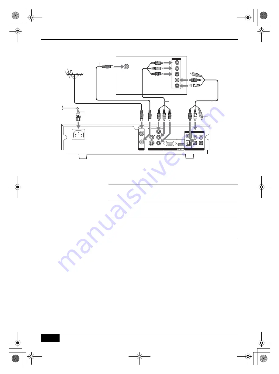
Connect your aerial cable to the socket labelled

 RF IN

 on the 

rear of the receiver.

2

Connect the supplied RF cable from the socket labelled

 RF 

OUT

 on the rear of the receiver to the aerial socket on your

TV/display screen.

3

Connect the supplied Y/Pb/Pr cable from the sockets labelled


Y

P

B

 and 

P

R

 on the rear of the receiver to the component input 

sockets on your TV/display screen.

4

Connect the supplied AV cable from the sockets labelled

 L

, and 

R

 on the rear of the receiver to the audio input sockets on your 

TV/display screen. (The yellow video jack does not need to be 
connected.) 

5

Connect the supplied AC cord from the AC IN socket on the 
rear of the receiver to your mains socket (100 - 240V AC,
50/60Hz).

Connecting to an HD TV/display screen via Component output

Rear of TV/display screen

Y/Pb/Pr 
cable 
(supplied)

AV cable (supplied)

Video jack 
(not required)

Video jack

(not required)

RF cable (supplied)

AC Cord
(supplied)

To mains

DST-HD100A.book  Page 8  Saturday, September 17, 2005  5:36 AM

Summary of Contents for DST-HD500

Page 1: ...2 663 710 11 2 DST HD500 2 663 710 11 2 High Definition Digital Receiver DST HD500 Operating Guide 2005 Sony Corporation MENU OK DST HD100A book Page 1 Saturday September 17 2005 5 36 AM ...

Page 2: ...iver with newspapers or curtains etc For ventilation leave a space of at least 10cm all around the receiver Never place the receiver in hot humid or excessively dusty places Do not install the receiver where it may be exposed to mechanical vibrations or electromagnetic radiation Clean the receiver with a soft lightly dampened cloth Do not use any type of abrasive pad alkaline cleaner scouring powd...

Page 3: ...i Fi Home Theatre etc 20 Using the remote control to operate other TVs 21 Specifications 22 Channels Available as of July 2004 23 Troubleshooting 24 Index 25 Should you experience a problem with this receiver please refer to the troubleshooting section on page 24 If you are unable to rectify the problem contact the Sony Australia Helpline on 1300 13 SONY 7669 Please ensure you have the following i...

Page 4: ...plied DST HD500 2 663 710 11 2 Batteries RF cable Remote control AC Cord Y Pb Pr Cable AV Cable RM X1022 TV 2 3 1 5 6 4 0 9 7 PROG DIGITAL TERRESTRIAL RECEIVER 8 OK RETURN LIST MENU DST HD100A book Page 4 Saturday September 17 2005 5 36 AM ...

Page 5: ...te These buttons only work once you have configured the remote control to operate your brand of TV refer to page 21 qs Standby button l 1 Press to switch off your receiver temporarily Press again to resume normal operation Note When the receiver is turned on it takes a few seconds for the system to warm up During this interval DST HD500 will be displayed in the front panel Please wait until the im...

Page 6: ...ftware upgrade RF output Audio Digital Optical output HD Component output S Video output Composite video output RF input Audio Analog L R output x2 1 Power indicator Remote control sensor Control pad V PROG v PROG B b and OK buttons HDMI output Audio Digital Coaxial output Note When the receiver is turned on it takes a few seconds for the system to warm up During this interval DST HD500 will be di...

Page 7: ... HDMI cable 1 Connect your aerial cable to the socket labelled RF IN on the rear of the receiver 2 Connect the supplied RF cable from the socket labelled RF OUT on the rear of the receiver to the aerial socket on your TV display screen 3 Connect an HDMI cable not supplied from the socket labelled HDMI on the rear of the receiver to the HDMI input socket on your TV display screen When using an HDMI...

Page 8: ...d PR on the rear of the receiver to the component input sockets on your TV display screen 4 Connect the supplied AV cable from the sockets labelled L and R on the rear of the receiver to the audio input sockets on your TV display screen The yellow video jack does not need to be connected 5 Connect the supplied AC cord from the AC IN socket on the rear of the receiver to your mains socket 100 240V ...

Page 9: ...ideo cable not supplied from the socket labelled S VIDEO on the rear of the receiver to the S Video input sockets on your TV display screen 4 Connect the supplied AV cable from the sockets labelled L and R on the rear of the receiver to the audio input sockets on your TV display screen The yellow video jack does not need to be connected 5 Connect the supplied AC cord from the AC IN socket on the r...

Page 10: ...lied RF cable from the socket labelled RF OUT on the rear of the receiver to the aerial socket on your TV display screen 3 Connect the supplied AV cable from the sockets labelled CVBS L and R on the rear of the receiver to the audio video input sockets on your TV display screen 4 Connect the supplied AC cord from the AC IN socket on the rear of the receiver to your mains socket 100 240V AC 50 60Hz...

Page 11: ...procedure A display appears showing a tuning progress bar and the channels found 4 When autotune procedure has finished the Program List is displayed showing all the available channels Press the OK button to remove the Program List and view the first channel captured Alternatively press the v button to select a different channel Press the OK button to remove the Program List and view the selected ...

Page 12: ...o display the Program List 3 Press the V or v buttons to highlight the required channel 4 Press the OK button to exit the Program List and display the selected channel To watch a Favorite channel 1 Press the MENU button to display the menu system 2 With the symbol highlighted press the V or v buttons to highlight Favorite List 1 or Favorite List 2 Press the b or OK buttons to display the Favorite ...

Page 13: ...on to highlight the required setting refer to table below Press the OK button to confirm Skip This option allows you to skip unwanted programs as you move through the channels by pressing PROG buttons With the Skip option highlighted press the b or OK button to confirm Press the V or v buttons to highlight the program to be skipped then press the OK button Press the V or v button to On To cancel t...

Page 14: ... the required setting refer to the table below Press the OK button to confirm Install Select Confirm EXIT BACK Quick Scan Manual Scan Program Edit Favorite Preset Parental Control Sets a parental rating and changes password Block All All programs need a password to view Block G and above To lock General and above programs Block PG and above To lock Parental Guidance and above programs Block M and ...

Page 15: ...ghtly disturbed during the transition between video formats This does not indicate a malfunction Aspect Ratio This option allows you to set the aspect ratio With the Aspect Ratio option highlighted press the b or OK button to adjust Press the V or v buttons to 16 9 Full Screen 4 3 Full Screen Crop or 4 3 Letter Box Press the OK button to confirm Note 16 9 Full Screen is for use with a widescreen T...

Page 16: ... OK button to adjust Press the B or b buttons to highlight Yes Press the OK button to confirm Once the receiver has restarted you will need to perform the initial tuning setup procedure refer to page 11 S W Update This option allows the software in your receiver to be upgraded It is recommended that this is performed ONLY by experienced Sony service personnel Please contact your local Sony service...

Page 17: ...isplay This feature gives you information on the current channel and also the current and next programs Press the button to display the i Plate This shows the date time whether the channel has teletext whether multi MPEG and Dolby Digital audio program available and whether the picture is available in high definition or standard definition HD or SD is displayed Press the b button to display inform...

Page 18: ...IN IN OUT AUDIO OUTPUT DIGITAL ANALOG S VIDEO Note Before connecting ensure all equipment is disconnected from the mains supply Connecting to an HD VCR DVD recorder Rear of VCR DVD recorder Y Pb Pr cable AV cable RF cable To TV aerial socket Connecting to an S Video VCR DVD recorder Rear of VCR DVD recorder S Video cable AV cable RF cable To TV aerial socket Video jack not required Video jack not ...

Page 19: ...VIDEO OUTPUT RS 232 RF OUT S VIDEO CVBS COAX L R V L R L R OPTICAL Y Pb Pr RF IN IN OUT AUDIO OUTPUT DIGITAL ANALOG Connecting to a Composite VCR DVD recorder Rear of VCR DVD recorder AV cable RF cable To TV aerial socket DST HD100A book Page 19 Saturday September 17 2005 5 36 AM ...

Page 20: ...ALOG Notes on connecting Hi Fi equipment This receiver can be connected to your Hi Fi using either a digital optical cable or an audio cable stereo mono Before connecting ensure all equipment is disconnected from the mains supply Connecting to a Hi Fi Home Theatre etc via audio cable Connecting to a Hi Fi Home Theatre etc via Optical output or Coaxial output Rear of Hi Fi Home Theatre etc Digital ...

Page 21: ...dure to re enter the code Even if your TV is listed in the table below in some instances you may not be able to operate all of the available TV functions Brand Code Brand Code Aiwa 036 055 Mitsubishi 045 Akai 059 060 062 063 064 065 066 067 068 Mivar 029 106 Beijing 022 NEC 020 053 058 063 094 097 Blaupunkt 071 Noblex 022 CGE 046 106 Nokia 031 059 097 Daewoo 017 037 069 Onwa 023 024 025 Ferguson 0...

Page 22: ...CA jacks S Video Mini Din HDMI HDMI jack Audio Formats Dolby Digital MPEG I and II Output Connector SPDIF Coaxial Digital RCA jacks Data Serial Data Port RS 232 OSD Number of Colours 256 Application System Resources CPU 306MIPS RAM Memory 64 MB SDRAM Flash Memory 2 MB Power Supply Input Voltage 100 240V AC 50 60Hz Consumption max 18W Dimensions Size W x D x H Approx 360 x 270 x 80mm Weight Approx ...

Page 23: ...mitter Bickley Main Transmitter Bickley 1 1 2001 1 1 2001 1 1 2001 1 1 2001 1 1 2001 Sydney Digital 7 Digital 9 Digital 10 Digital ABC Digital SBS VHF 6 177 5MHz VHF 8 191 625MHz VHF 11 219 5MHz VHF 12 226 5MHz UHF 34 571 5MHz Main Transmitter Artarmon Main Transmitter Willoughby Main Transmitter Artarmon Main Transmitter Gore Hill Main Transmitter Gore Hill 1 1 2001 1 1 2001 1 1 2001 1 1 2001 1 1...

Page 24: ...ometimes the preferred audio service is set in the left or right channel only Please refer to Audio Select 5 No video service If there is a music banner being displayed then there is ONLY audio available on this channel for example a radio channel 6 Does not have all the channels available after using Auto Scan when installing the receiver a b Try Full Scan to scan the missing channels instead of ...

Page 25: ... G H I J K Information 16 Install menu 13 i Plate display 17 L M N Manual Scan 13 Menu system general operation 12 MPEG Volume Control 15 O Overview receiver 6 remote control 5 P Q Parental Contorol 14 Parental Rating 14 Picture Freeze 17 Picture In Picture PIP 17 Program Edit 13 Program List 12 Program Sorting 13 Quick Scan 13 R Receiver overview 6 Remote control of TV 21 Remote control overview ...

Page 26: ...DST HD500 2 663 710 11 2 DST HD100A book Page 26 Saturday September 17 2005 5 36 AM ...

Page 27: ...DST HD500 2 663 710 11 2 DST HD100A book Page 27 Saturday September 17 2005 5 36 AM ...

Page 28: ...DST HD500 2 663 710 11 2 Recyclable Sony Corporation Printed in Taiwan DST HD500 Sony Corporation Printed in Taiwan DST HD100A book Page 28 Saturday September 17 2005 5 36 AM ...

Reviews: