2-3
DSC-W90_L2
EXPLODED VIEW
HARDWARE LIST
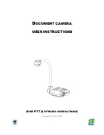
2-2. DISASSEMBLY
2-2-1. CABINET SECTION
Follow the disassembly in the numerical order given.
1
Cabinet (Front) (
1
-1 to
1
-8)
2
Cabinet (Rear) (
2
-1 to
2
-2)
HELP
HELP
Note: On installation of the cabinet (rear),
adjust the position of the mode dial
switch and the mode dial.
1
Cabinet (Front)
Main Board Section
(See Page 2-4)
2
-1 (#65)
2
-2 (#65)
1
-1 (#65)
1
-4 (#65)
1
-5
(#65)
1
-6 (#65)
1
-7 (Open)
1
-8
(Claw)
1
-2 (Claw)
1
-3
2
Cabinet
(Rear)
HELP