background image

4-2

DCR-HC51E/HC52/HC52E/HC53E/HC54/HC54E_L2

4-2. SCHEMATIC DIAGRAMS

4-2. SCHEMATIC DIAGRAMS

4-2. SCHEMATIC  DIAGRAMS

1. Connection

2. Adjust the distance so that the output waveform of

Fig. a and the Fig. b can be obtain.

When indicating parts by reference number, please
include the board name.

(For schematic diagrams)

• All capacitors are in 

µ

F unless otherwise noted. pF : 

µ

µ

F.  50 V or less are not indicated except for electrolytics

and tantalums.

• Chip resistors are 1/10 W unless otherwise noted.

k

=1000 

, M

=1000 k

.

• Caution when replacing chip parts.

New parts must be attached after removal of chip.
Be careful not to heat the minus side of tantalum
capacitor, Because it is damaged by the heat.

• Some chip part will be indicated as follows.

Example

C541

L452

22U

10UH

TA  A

2520

• Constants of resistors, capacitors, ICs and etc with XX

indicate that they are not used.
In such cases, the unused circuits may be indicated.

• Parts with 

 differ according to the model/destination.

Refer to the mount table for each function.

• All variable and adjustable resistors have characteristic

curve B, unless otherwise noted.

• Signal name

XEDIT


EDIT

PB/XREC 

 PB/REC

2

: non flammable resistor

5

: fusible resistor

C

: panel designation

A

: B+ Line

B

: B– Line

J

: IN/OUT direction of (+,–) B LINE.

C

: adjustment for repair.

A

: not use circuit

(Measuring conditions voltage and waveform)

• Voltages and waveforms are measured between the

measurement points and ground when camera shoots
color bar chart of pattern box. They are reference values
and reference waveforms.
(VOM of DC 10 M

 input impedance is used)

• Voltage values change depending upon input

impedance of VOM used.)

Kinds of capacitor

Case size

External dimensions (mm)

Y

ellow

A

A

B

B

A=B

Fig. a (Video output terminal output waveform)

H

Cyan

Green

White

Magenta

Red

Blue

Fig.b (Picture on monitor TV)

CRT picture frame

Electronic beam
scanning frame

THIS NOTE IS COMMON FOR SCHEMATIC DIAGRAMS
(In addition to this, the necessary note is printed in each block)

Pattern box

Pattern box PTB-450
J-6082-200-A
 or
Small pattern box
PTB-1450
J-6082-557-A

Color bar chart

For PTB-450:
J-6020-250-A

For PTB-1450:
J-6082-559-A

Pattern box

Front of the lens

L = 1 m (PTB-450)
L = 40 cm (PTB-1450)

L

Camera

Precautions for Replacement of Imager

• If the imager has been replaced, carry out all the adjustments

for the camera section.

• As the imager may be damaged by static electricity from

its structure, handle it carefully like for the MOS IC.
In addition, ensure that the receiver is not covered with
dusts nor exposed to strong light.

The components identified by mark 

0

 or dotted line with

mark 

0

 are critical for safety.

Replace only with part number specified.

Les composants identifiés par une marque 

0

  sont

critiques pour la sécurité.
Ne les remplacer que par une pièce portant le numéro
spécifie.

Summary of Contents for DCR-HC52

Page 1: ...224 31 Photo DCR HC52 The components identified by mark 0 or dotted line with mark 0 are critical for safety Replace only with part num ber specified Les composants identifiés par une marque 0 sont critiques pour la sécurité Ne les remplacer que par une pièce portant le numéro spécifié Precaution on Replacing the VC 537 Board N MECHANISM MDX N220 US Model Canadian Model AEP Model UK Model East Eur...

Page 2: ...d including the projecting parts 63 85 115 mm 2 1 2 3 3 8 4 5 8 in w h d including the projecting parts with supplied battery pack NP FH30 attached Mass approx 380g 13oz main unit only 440g 15oz including the NP FH30 rechargeable battery pack and DVM60 cassette Supplied accessories AC Adaptor AC L200 L200B Power requirements AC 100 V 240 V 50 60 Hz Current consumption 0 35 0 18 A Power consumption...

Page 3: ...requirements DC 6 8 V 7 2 V battery pack DC 8 4 V AC Adaptor Average power consumption During camera recording using the viewfinder 1 8 W During camera recording using the LCD 2 1 W Operating temperature 0 C to 40 C 32 F to 104 F AC Adaptor AC L200 L200B Power requirements AC 100 V 240 V 50 60 Hz Current consumption 0 35 0 18 A Power consumption 18 W Output voltage DC 8 4 V Operating temperature 0...

Page 4: ...ian model EE East European model KR Korea model MX Mexican model NE North European model Model information table HC51E AEP UK NE EE PAL OUT Model Destination Color system DV i LINK Interface USB jack HC53E AEP UK NE EE PAL OUT HC52 NTSC IN OUT HC52E NE AUS CH E US CND MX BR AR KR E PAL IN OUT HC54 CND AR E NTSC IN OUT HC54E NE CH E PAL IN OUT ...

Page 5: ...erform the following safety checks before releasing the set to the customer ATTENTION AU COMPOSANT AYANT RAPPORT À LA SÉCURITÉ LES COMPOSANTS IDENTIFÉS PAR UNE MARQUE 0 SUR LES DIAGRAMMES SCHÉMATIQUES ET LA LISTE DES PIÈCES SONT CRITIQUES POUR LA SÉCURITÉ DE FONCTIONNEMENT NE REMPLACER CES COMPOSANTS QUE PAR DES PIÈSES SONY DONT LES NUMÉROS SONT DONNÉS DANS CE MANUEL OU DANS LES SUPPÉMENTS PUBLIÉS...

Page 6: ...ly 4 5Vdc 1 3 SETTING THE FORCED POWER ON MODE It is possible to turn on power by adjustment remote commander RM 95 or NEW LANC JIG Operate the VTR function using the adjustment remote commander 1 3 1 Setting the Forced Camera Power ON Mode 1 Select page 0 address 01 and set data 01 2 Select page A address 10 set data 01 and press the PAUSE Write button of the adjustment remote commander 1 3 2 Set...

Page 7: ...habet and numbers which blinks at 3 2 Hz This 5 character display indicates the repaired by block in which the problem occurred and detailed code of the problem 1 1 3 1 C Repaired by Refer to 1 5 3 Self diagnosis Code Table Indicates the appropriate step to be taken E g 31 Reload the tape 32 Turn on power again Block Detailed Code Blinks at 3 2Hz C Corrected by customer H Corrected by dealer E Cor...

Page 8: ...rform operations from the beginning Load the tape again and perform operations from the beginning Load the tape again and perform operations from the beginning Load the tape again and perform operations from the beginning Load the tape again and perform operations from the beginning Load the tape again and perform operations from the beginning Load the tape again and perform operations from the be...

Page 9: ...ve circuit IC3101 of VC 537 board when zooming is not performed Inspect the flexible board for breakage or loose connection If not faulty inspect the focus and zoom motor drive circuit IC3101 of VC 537 board 1 6 PRECAUTION ON REPLACING THE VC 537 BOARD Exif Model Data Check When you replace to the repairing board the written data of repairing board also might be changed to original setting When th...

Page 10: ... Do not insert the cable insufficiently nor crookedly When remove a connector don t pull at wire of connector It is possible that a wire is snapped When installing a connector don t press down at wire of connector It is possible that a wire is snapped Cut and remove the part of gilt which comes off at the point Be careful or some pieces of gilt may be left inside ...

Page 11: ...ON VC 537 Board CD 735 Board Lens Device LSV 1171A Mechanism Deck Control Key Block SS21200 2 2 4 CABINET R SECTION Loud Speaker CF 111 Board LCD Panel Block BT EVF Section LB 137 Board AV 125 Board FP 626 Flexible Board Cabinet L Section VC 537 Board CD 735 Board Cabinet R Section CF 111 Board PD 358 Board FP 386 Flexible Board FP 625 Flexible Board Front Cabinet Block Bottom Frame DISASSEMBLY FL...

Page 12: ...ront Cabinet Block 2 1 to 2 6 HELP HELP EXPLODED VIEW HARDWARE LIST 1 Cabinet R Section See Page 2 6 1 1 Open 1 2 2 1 3 1 4 1 5 2 1 2 2 3 2 4 1 2 5 1 2 6 2 2 2 Note On installation of the NS knob adjust the position of the NS switch and the NS knob 1 12 Boss 1 11 Boss 1 6 2 1 7 2 1 14 1 13 1 9 2 1 8 Open 2 Front Cabinet Block 1 10 Claw Bottom Frame Section See Page 2 4 ...

Page 13: ...T EVF Section 1 1 to 1 3 2 JK 367 Board 2 1 to 2 7 EXPLODED VIEW HARDWARE LIST Cabinet L Section See Page 2 5 1 BT EVF Section 1 2 1 3 1 1 2 2 4 2 6 2 2 2 3 1 2 1 2 5 Claw 2 JK 367 Board 2 7 3 Note On installation of the bottom frame insert the claw of the bottom frame to the hole of the MD frame Claw Bottom Frame Hole MD Frame ...

Page 14: ...isassembly in the numerical order given 1 Lens Block 1 1 to 1 3 2 VC 537 Board 2 1 to 2 8 3 Mechanism Deck 3 1 to 3 3 EXPLODED VIEW HARDWARE LIST 2 VC 537 Board 3 Mechanism Deck 1 1 1 3 1 2 12 2 1 2 2 2 8 2 3 2 7 3 3 15 3 2 2 4 3 2 5 Claw 3 1 Claw VC 537 2 6 Claw 1 Lens Block HELP01 ...

Page 15: ...erical order given 1 CF 111 Board 1 1 to 1 7 2 LCD Panel Block 2 1 to 2 4 EXPLODED VIEW HARDWARE LIST 1 CF 111 Board 1 1 1 4 1 5 12 2 2 2 1 12 2 3 12 1 7 Claw 2 LCD Panel Block 1 2 12 1 6 12 Note On installation of the CF 111 board adjust the position of the Panel Open Close switch 1 3 2 4 HELP02 HELP03 ...

Page 16: ...ELP Sheet attachment positions and procedures of processing the flexible boards harnesses are shown Harness arrangement Plating Lead Lens Device LSV 1171A Loud Speaker CF 111 Board F Insulating Sheet Sticking Standard Sticking Standard HELP01 HELP02 ...

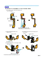
Page 17: ...Fix hinge cover M and the panel hinge assy M with the screw Screw Hinge cover M FP 625 flexible board Hinge cover M 1 Fold dotted line parts of the FP 625 flexible board as shown in figure Valley fold Mountain fold Stick it together in the adhesive tape while bending the FP 625 flexible board Mountain fold Valley fold Adhesive tape Adhesive tape THE METHOD OF ATTACHMENT OF FP 625 FLEXIBLE BOARD HE...

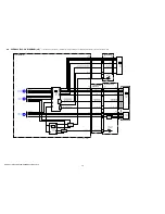
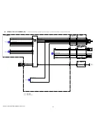
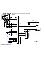
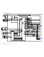
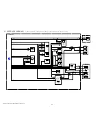
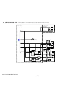
Page 18: ...54E_L2 Link Link 3 BLOCK DIAGRAMS OVERALL BLOCK DIAGRAM 4 5 OVERALL BLOCK DIAGRAM 3 5 OVERALL BLOCK DIAGRAM 2 5 OVERALL BLOCK DIAGRAM 1 5 POWER BLOCK DIAGRAM 3 3 POWER BLOCK DIAGRAM 2 3 POWER BLOCK DIAGRAM 1 3 OVERALL BLOCK DIAGRAM 5 5 ...

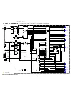
Page 19: ...SB_D USB_D USB_D USB_D USB_D USB_DET D24A00 D31A07 DXXA08 DXXA09 ALE WRX RDX D24A00 D31A07 DXXA08 DXXA09 ALE WRX RDX 78 77 96 OVERALL 2 5 PAGE 3 2 2 OVERALL 4 5 PAGE 3 4 4 OVERALL 3 5 PAGE 3 3 3 OVERALL 4 5 PAGE 3 4 5 OVERALL 3 5 PAGE 3 3 6 OVERALL 4 5 PAGE 3 4 7 OVERALL 2 5 PAGE 3 2 8 RECDT RECA1 RECA2 RECCK RFIN DATA_TO_SFD SFD_BCK DATA_FROM_SFD SFD_FCK SFD_LRCK IC_6001_C_OUT IC_6001_Y_OUT 63 68...

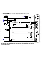
Page 20: ...M_FG_SENS 59 DRUM_COM 51 FG_PG_COM DRUM_PG_SENS LED DRIVE TAPE_LED_K 1 IC8602 EEPROM 10 13 D1 C1 X8601 20MHz XCS_EEP F1 SERIAL INTERFACE 38 36 77 78 64 67 63 65 68 74 76 78 75 77 1 80 10 15 7 8 75 76 37 XCS_IC_9001_1 34 XRST_VTR OVERALL 1 5 PAGE 3 1 1 OVERALL 1 5 PAGE 3 1 8 F2 XSYS_RST F4 LM_LIM_DET LM_LIM_DET 41 35 SPCK SPCK EEP_SI EEP_SO EEP_SCK OVERALL 1 5 PAGE 3 1 2 OVERALL 5 5 PAGE 3 5 10 REC...

Page 21: ...N6405 HCK1 HCK2 HST PCG EN VCK VST WIDE PSIG REF 33 32 6 9 12 14 16 17 24 30 LCD901 31 5 3 7 6 1 2 43 3 LCD BACKLIGHT DRIVE Q9312 Q9315 XSYS_RST VR VG VB COM CS 18 16 17 CN302 D302 BACKLIGHT D6403 D6405 BACKLIGHT EVF_VR EVF_VG EVF_VB EVF_COM_CS 14 13 17 15 CN9301 EVF_HCK1 EVF_HCK2 EVF_HST EVF_PCG EVF_EN EVF_VCK EVF_VST WIDE EVF_VP EVF_REF HCK1 HCK2 HST PCG EN VCK VST WIDE PSIG REF HCK1 HCK2 HST PC...

Page 22: ...47 BEEP XCS_AU1 IC_6001_C_OUT IC_6001_Y_OUT CN402 VIDEO_I O MULTI_JACK_IN AUDIO_L_I O AUDIO_R_I O S_C_I O S_Y_I O MULTI_JACK_IN VIDEO_OUT AUDIO_L_I O AUDIO_R_I O S_C_OUT S_Y_OUT VIDEO_IN OUT S C S Y JACK_AD AUDIO_R AUDIO_L AV 125 BOARD FP 626 FLEXIBLE BOARD 1 2 26 27 29 28 24 23 LANC_SIG 10 5 9 1 6 7 A V R CN401 4 LANC_SIG LANC_SIG 21 2 11 8 9 3 5 6 A VIDEO SIGNAL A AUDIO SIGNAL A VIDEO AUDIO SIGN...

Page 23: ...ONTROL KEY BLOCK SS21200 START STOP S008 RV002 ZOOM W T 1 CAMERA D006 3 9 10 4 PLAY EDIT D005 S006 EJECT POWER CONTROL KEY BLOCK SB9000 S001 S002 S003 ZOOM T W 4 5 3 S101 PANEL REVERSE PANEL_REVERSE 2ND_ZOOM T 2ND_ZOOM W 2ND_S S_SW FP 386 FLEXIBLE BOARD RESET S801 LI_3V S804 PANEL OPEN CLOSE EASY CHG S803 BACKLIGHT S805 CF 111 BOARD 2 3 DISP BATT INFO S802 D801 CN1002 2 3 4 3 5 1 CN802 2 3 7 8 6 1...

Page 24: ...Sck BATT_SIG XLANC_PWR_ON XLANC_ON VTR_DD_ON XCS_DD BATT_IN INIT_CHARGE_ON FAST_CHARGE BATT XEXT SIO2 initCharge fastCharge batt_xExt G2 BATT XEXT_CR batt_xExt_cra VOUT HI_EVER_SO HI_EVER_SCK IC2201 DC CONTROL RESET LANC DRIVE DRUM CAPSTAN PWM DRIVE 3 13 44 13 55 52 CAM_DD_ON 5 50 45 49 64 12 46 58 15 14 D2201 VCC2 60 VCC3 61 VCC1 WAKE_UP XCTL2 LD REG6CTL OUTC1 CTL1 DIN CLK VBATT VOUT3 VOUT4 OUT1 ...

Page 25: ... FB6002 HU HV HW CAPSTAN FG MIC902 4PIN CONNECTOR D901 TAPE LED H901 S REEL SENSOR H902 T REEL SENSOR S H AGC A D CONVERTER TIMING GENERATOR 4 13 IC3001 CN3001 CN7101 CD 735 BOARD CCD IMAGER 14 IC7101 1 13 2 FOCUS ZOOM MOTOR DRIVE 5 13 IC3101 L3001 L3101 VTR_UNREG D_1 5V D_1 5V MT_5V A_2 8V AU_4 6V L6502 L6501 IC6501 REC PB AMP 7 13 RP_2 8V RP_4 6V USB_3 1V IC_9001_13 5V VTR_UNREG IC_9001_13 5V CA...

Page 26: ...5 6 CN9302 25 VDD_P XSTBY PD 358 BOARD 18 CN6405 VDD 14 XSTBY CN6401 25 6 8 D_2 8V D_2 8V 23 POFF 2 5 inch COLOR LCD MONITOR LCD901 Q9316 9307 D_2 8V NS 2 8V D1026 NIGHTSHOT LB 137 BOARD 2 CN302 VDD 1 CN9301 19 CN301 2 20 L9302 L9301 L9303 EVF_VDD 11 STB 7 14 EVF_STB EP_4 6V COLOR EVF UNIT D302 BACKLIGHT LCD902 LCD EVF DRIVE 13 13 IC9301 LCD EVF BACKLIGHT CONTROL 13 13 IC9302 EP_8 5V A_4 6V EP_4 6...

Page 27: ...S BLOCK MIC901 MICROPHONE UNIT FOR CHECK CPC CD 735 BOARD SIDE A PD 358 BOARD CD 735 BOARD SIDE B LB 137 BOARD LCD902 COLOR EVF UNIT BATTERY TERMINAL BOARD C DC IN FP 626 FLEXIBLE BOARD JK 367 BOARD CONTROL KEY BLOCK SS21200 BH001 J001 1 30 1 12 AV 125 BOARD SIDE A AV 125 BOARD SIDE B A V R DV USB HC53E HC54 HC54E FP 228 FLEXIBLE BOARD FP 032 FLEXIBLE BOARD FP 031 FLEXIBLE BOARD N MECHANISM DECK M...

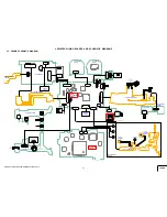
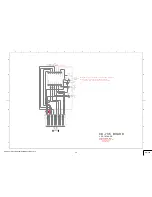
Page 28: ... FLEXIBLE BOARD VC PD CONNECTION FP 626 FLEXIBLE BOARD DC IN AV 125 BOARD AV CONNECTOR CONTROL KEY BLOCK SB9000 JK 367 BOARD DV USB CONNECTOR CF 111 BOARD CONTROL SWITCH CD 735 BOARD CCD IMAGER PD 358 BOARD LCD LCD BACKLIGHT FP 031 FP 032 FP 228 FLEXIBLE BOARD CONTROL KEY BLOCK SS21200 Link Link COMMON NOTE FOR SCHEMATIC DIAGRAMS ...

Page 29: ...it Measuring conditions voltage and waveform Voltages and waveforms are measured between the measurement points and ground when camera shoots color bar chart of pattern box They are reference values and reference waveforms VOM of DC 10 MΩ input impedance is used Voltage values change depending upon input impedance of VOM used Kinds of capacitor Case size External dimensions mm Yellow A A B B A B F...

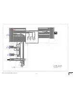
Page 30: ... 3 1 4 IC7101 CCD IMAGER 1 2 3 4 5 6 7 8 9 10 11 12 13 14 C7101 10u 16V C7102 XX C7105 10p C7104 10u 16V C L 7 1 0 2 C7107 XX R 7 1 0 3 X X C L 7 1 0 1 C7103 0 01u L 7 1 0 1 1 0 u H Q7101 2SC3931G0LS0 R E G _ G N D V 3 V 2 V 2 R G H 2 V 4 R E G _ G N D V S H T C A M _ 7 5 V G N D R G V 4 V L V 3 H 1 V 1 V 1 H 1 C C D _ O U T R E G _ G N D V H H 2 V _ D R A I N G N D V S H T C C D _ O U T C A M _ 1...

Page 31: ...DCR HC51E HC52 HC52E HC53E HC54 HC54E_L2 Schematic diagrams of the VC 537 board are not shown Pages from 4 4 to 4 16 are not shown ...

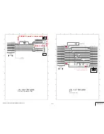
Page 32: ...7 XX D6406 XX R6430 XX R6429 XX CL6401 CL6402 CL6403 CL6404 D6410 XX 3 2 1 VD6402 VD6401 VD6403 VD6404 CN6401 30P 1 2 3 4 5 6 7 8 9 10 11 12 13 14 15 16 17 18 19 20 21 22 23 24 25 26 27 28 29 30 CN6403 6P 1 2 3 4 5 6 CN6404 6P 1 2 3 4 5 6 D6402 MAZS056G08S0 VST WIDE VDD PANEL_REVERSE TP_R G TP_BOT HCK1 RGT CS REG_GND TEST1 HST TEST2 N C DWN REG_GND PCG N C COM PANEL_REVERSE EN R VSSG PSIG 2ND_ZOOM...

Page 33: ...112 A V R AV 125 BOARD Note BT901 LITHIUM STORAGE BATTERY and SP901 SPEAKER are not included in CF 111 complete board BH801 CN801 2P 1 2 D801 CL 271TLY C TS D803 XX 3 2 1 D802 XX 1 2 6 5 4 3 LND802 LND801 R801 1500 R802 2200 S801 1 3 2 4 S802 1 3 2 4 S805 1 3 2 4 S803 1 3 2 4 S804 CN802 10P 1 2 3 4 5 6 7 8 9 10 CHASSIS_GND CHARGE_LED_VDD LI_3V XRESET SP KEY_AD3 SP BATT_INFO XCHARGE_LED GND REG_GND...

Page 34: ...ot included in LB 137 complete board C301 0 1u C302 1u C303 XX CN302 21P 1 2 3 4 5 6 7 8 9 10 11 12 13 14 15 16 17 18 19 20 21 D302 NESW007AT T099 R304 1M R303 XX CN301 20P 1 2 3 4 5 6 7 8 9 10 11 12 13 14 15 16 17 18 19 20 D301 MAZS056G08S0 COM EVF_BLK EVF_GND EVF_VDD EVF_VST EVF_HCK2 HCK2 EP_4 6V EVF_HCK1 VR HCK1 PSIG EVF_PSIG EVF_PCG VDD STB EVF_REF VSS EN VB EVF_COM_CS EVF_EN RGT VST PCG EVF_V...

Page 35: ...109 LND105 LND116 LND115 LND019 LND018 LND017 LND020 LND021 LND022 LND120 LND122 LND119 LND121 LND117 LND118 LND124 LND023 LND123 LND024 LND125 LND025 LND026 LND126 LND127 LND027 LND028 LND128 LND129 LND029 LND130 LND030 BL_H3 DWN XSTBY VDD_P VCK HCK2 RGT D_2 8V REG_GND HCK1 TP_Y REG_GND TP_X REG_GND BL_H1 PANEL_VR REG_GND TP_SEL1 WIDE PANEL_VG REF KEY_AD1 BL_H2 EN PANEL_VB PSIG PCG COM VST HST HC...

Page 36: ...G N C S_C_I O REG_GND BATT_UNREG BATT_UNREG REG_GND LANC_SIG ACV_UNREG BATT_UNREG REG_GND BATT_SIG N C AUDIO_R_I O LANC_DC LANC_SIG S_Y_I O VIDEO_I O S_C_I O MULTI_JACK_IN REG_GND REG_GND REG_GND REG_GND AUDIO_L_I O CHASSIS_GND D E A 3 D A F C C E 2 4 1 F 08 B B DC IN VC 537 PAGE 4 5 2 13 of LEVEL3 CN2001 29 28 2 1 3 Pin 30 AV 125 PAGE 4 18 of LEVEL2 CN401 BATTERY TERMINAL BOARD DC IN 10 11 12 Pin...

Page 37: ...3 D004 XX LND027 D006 LND037 LND032 L N D 0 3 8 LND025 LND035 LND030 XEJECT_SW XCAM_LED N C REG_GND XPOWER_SW XPOWER_SW ZOOM_VR XMODE_SW REG_GND D_2 8V XVTR_LED MODE_LED_VDD XMODE_SW R E G _ G N D KEY_AD5 SS REG_GND 20k N C 08 C A B D E D 3 B F 2 C 1 8 6 A 5 7 F 4 E XX MARK NO MOUNT W ZO0M T PLAY EDIT CAMERA EJECT START STOP VC 537 PAGE 4 4 1 13 of LEVEL3 CN1012 MODE ON CHG OFF POWER 3 14 13 1 2 P...

Page 38: ...02 LOADING MOTOR G Vcc G Vcc H902 HW 105A CDE T T REEL SENSOR H901 HW 105A CDE T S REEL SENSOR 08 Q901 PT4850FJE00F TAPE END SENSOR LM_LOAD LM_LOAD LM_UNLOAD LM_UNLOAD DEW DEW XMODE_SW_A XMODE_SW_B XMODE_SW_C SW_COM XREC_PROOF CHIME_VDD CHIME_SDA CHIME_SCK MIC REC_SW_GND TAPE_TOP XCCDOWN_SW Cin_GND TREEL TREEL HALL_VCC SREEL SREEL HALL_GND TAPE_LED_K TAPE_LED_A TOP END_GND TAPE_END 1 2 3 4 5 6 7 8...

Page 39: ...E_L2 Link Link CD 735 BOARD PD 358 BOARD SIDE B PD 358 BOARD SIDE A CF 111 BOARD SIDE A CF 111 BOARD SIDE B AV 125 BOARD LB 137 BOARD JK 367 BOARD FP 386 FLEXIBLE BOARD FP 626 FLEXIBLE BOARD FP 031 FP 032 FP 228 FLEXIBLE BOARD COMMON NOTE FOR PRINTED WIRING BOARDS ...

Page 40: ...other layers patterns are not indicated Through hole is omitted There are a few cases that the part printed on diagram isn t mounted in this model C panel designation THIS NOTE IS COMMON FOR PRINTED WIRING BOARDS 4 3 PRINTED WIRING BOARDS 2 1 3 2 1 3 2 1 3 3 4 5 2 1 1 2 3 6 5 4 E B C 3 1 5 2 4 6 1 2 3 6 5 4 3 1 5 2 4 6 1 2 3 5 4 4 3 1 2 3 1 2 4 5 5 3 4 1 2 1 4 2 3 4 6 2 5 3 1 1 2 4 3 1 4 2 3 Chip ...

Page 41: ...rs Uses unleaded solder 1 14 CN7101 C7101 C7102 C7103 C7104 C7105 Q7101 C7106 C7107 R7101 R7102 R7103 L7101 C B E CL7101 CL7102 14 1 8 7 IC7101 CD 735 BOARD SIDE A CD 735 BOARD SIDE B 08 1 875 081 11 08 IC7101 is not included in CD 735 complete board Note 1 875 081 11 ...

Page 42: ...DCR HC51E HC52 HC52E HC53E HC54 HC54E_L2 Printed wiring boards of theVC 537 board are not shown Pages 4 26 and 4 27 are not shown ...

Page 43: ... CN6402 CN6403 CN6404 CN6405 C6402 C6403 C6404 Q6401 C6405 Q6402 C6406 Q6403 D6401 D6402 R6401 R6402 D6406 R6403 D6407 R6404 D6408 R6406 R6407 D6410 R6411 R6414 R6415 VD6401 VD6402 VD6403 VD6404 R6426 R6429 R6430 R6431 LND641 LND642 LND643 C6401 1 3 4 6 1 3 4 6 1 3 4 6 1 2 3 PD 358 BOARD SIDE A 08 1 875 082 11 PD 358 2 layers Uses unleaded solder PD 358 SIDE A ...

Page 44: ...52E HC53E HC54 HC54E_L2 Note LCD901 is not included in PD 358 complete board D6403 D6404 D6405 A K A K A K PD 358 BOARD SIDE B 08 BACKLIGHT BACKLIGHT BACKLIGHT 1 875 082 11 PD 358 SIDE B PD 358 2 layers Uses unleaded solder ...

Page 45: ... AV 125 BOARD SIDE A 1 875 085 AV 125 BOARD SIDE B 11 08 A V R 08 1 875 085 11 1 10 7 6 9 8 1 5 1 2 3 4 5 6 CN101 CN104 LND101 CN103 RB101 D101 1 7 2 8 JK 367 BOARD SIDE A USB DV 1 875 083 11 08 JK 367 BOARD SIDE B 1 875 083 11 08 Note LCD902 is not included in LB 137 complete board 1 2 19 20 1 2 21 20 CN301 CN302 R303 R304 C301 C302 C303 D301 D302 LB 137 BOARD SIDE A LB 137 BOARD SIDE B 1 875 084...

Page 46: ... HC54E_L2 CF 111 2 layers Uses unleaded solder S801 S802 S803 S804 S805 D801 LND801 LND802 1 2 3 4 1 2 3 4 1 K A 2 3 4 1 2 1 2 3 4 CF 111 BOARD SIDE A 1 875 086 11 08 CHG EASY BACKLIGHT DISP BATT INFO RESET PANEL OPENL CLOSE CF 111 SIDE A ...

Page 47: ...DE B 08 BT901 LITHIUM STORAGE BATTERY 1 875 086 11 CF 111 2 layers CF 111 SIDE B CAUTION Danger of explosion if battery is incorrectly replaced Replace only with the same or equivalent type Note Replace the battery holder BH801 together when replacing the lithium storage battery BT901 on the CF 111 board The battery holder removed once cannot be used again When mounting these parts mount new batte...

Page 48: ...ND028 LND027 LND026 LND025 LND024 LND023 LND022 LND021 LND020 LND019 LND018 LND017 LND016 LND015 LND014 LND013 LND012 LND011 LND010 LND009 LND008 LND007 LND006 LND005 LND004 LND003 LND002 LND001 LND107 LND108 LND109 LND110 LND111 LND112 11 1 871 485 1 1 2 1 2 3 4 1 30 12 BH001 BATTERY TERMINAL BOARD C Note BH001 and J001 are not included in FP 626 flexible board J001 DC IN 08 FP 626 FLEXIBLE BOARD...

Page 49: ...ese parts requires high accuracy DEW SENSOR M902 LOADING MOTOR S903 MODE SWITCH M Dilect Solder Dilect Solder 1 1 4 2 1 677 049 11 12 1 864 865 12 13 1 867 811 11 12 29 1 S902 REC PROOF S901 CC DOWN D901 TAPE LED H902 T REEL SENSOR H901 S REEL SENSOR MIC902 Q902 TAPE TOP SENSOR 4 PIN CONNECTOR Q901 TAPE END SENSOR GND VCC GND VCC 08 FP 031 FLEXIBLE BOARD FP 228 FLEXIBLE BOARD FP 032 FLEXIBLE BOARD...

Page 50: ...E Characters A to Z of the electrical parts list indicate location of exploded views in which the desired part is shown LS MECHANICAL CHASSIS BLOCK ASSEMBLY 2 A B C D E F H I G ACCESSORIES CF 111 BOARD CD 735 BOARD AV 125 BOARD FP 228 FLEXIBLE BOARD FP 032 FLEXIBLE BOARD FP 031 FLEXIBLE BOARD FP 386 FLEXIBLE BOARD FP 625 FLEXIBLE BOARD FP 626 FLEXIBLE BOARD JK 367 BOARD LB 137 BOARD PD 358 BOARD D...

Page 51: ...TORS All resistors are in ohms METAL metal film resistor METAL OXIDE Metal Oxide film resistor F nonflammable SEMICONDUCTORS In each case u µ for example uA µA uPA µPA uPB µPB uPC µPC uPD µPD When indicating parts by reference number please include the board name The components identified by mark 0 or dotted line with mark 0 are critical for safety Replace only with part number specified Les compo...

Page 52: ...EXIBLE FLAT FFC 085 5 2 899 716 01 RETAINER MICROPHONE 6 2 899 717 01 CUSHION MICROPHONE 7 X 2186 671 1 PANEL 2122 ASSY F HC51E HC52 HC52E 7 X 2186 798 1 PANEL 2132 ASSY F HC53E HC54 HC54E MIC901 1 542 712 11 MICROPHONE UNIT 1 2 635 562 11 SCREW M1 7 Black 2 2 635 562 31 SCREW M1 7 Black 12 3 080 204 21 SCREW TAPPING P2 Black 5 1 1 OVERALL SECTION 5 1 EXPLODED VIEWS 7 1 2 2 2 1 1 2 2 2 2 12 2 3 5 ...

Page 53: ...OM 53 1 833 211 11 CABLE FLEXIBLE FLAT FFC 090 54 A 1438 778 A JK 367 BOARD COMPLETE HC51E HC52 HC52E 54 A 1438 779 A JK 367 BOARD COMPLETE HC53E HC54 HC54E 1 2 635 562 11 SCREW M1 7 Black 2 2 635 562 31 SCREW M1 7 Black 3 2 660 401 01 SCREW M1 7 NEW TRU STAR P2 Red 5 1 2 BOTTOM FRAME SECTION 54 53 52 51 2 3 1 Cabinet L Section See Page 5 4 BT EVF Section See Page 5 7 DISASSEMBLY HARDWARE LIST ...

Page 54: ...1 DEVICE LENS LSV 1171A 108 A 1496 718 A VC 537 BOARD COMPLETE SERVICE HC51E HC52 HC52E 108 A 1496 719 A VC 537 BOARD COMPLETE SERVICE HC53E HC54 HC54E 109 2 659 500 01 LABEL FUSE REPLACEMENT CAUTION HC51E HC52 US HC52E NE E HC53E HC54E NE E 110 3 095 521 01 SHEET GUARD 111 2 675 602 01 SHEET F INSULATING IC7101 8 753 244 70 ICX610NKF 13 CCD IMAGER HC52 HC54 Note 1 2 IC7101 8 753 244 71 ICX611NKF ...

Page 55: ...AGE LITHIUM Note SP901 1 825 260 51 LOUD SPEAKER 1 6CM 12 3 080 204 21 SCREW TAPPING P2 Black CAUTION Danger of explosion if battery is incorrectly replaced Replace only with the same or equivalent type Refer to page 5 1 for mark 0 Note Replace the battery holder BH801 together when replac ing the lithium storage battery BT901 on the CF 111 board The battery holder removed once cannot be used agai...

Page 56: ... 01 REFLECTION SHEET 2 5 211 A 1438 760 A PD 358 BOARD COMPLETE 212 3 268 972 01 SHEET P MIRROR HC52 HC52E 212 3 268 972 11 SHEET P MIRROR HC54 HC54E 212 3 268 972 31 SHEET P MIRROR HC51E 212 3 268 972 41 SHEET P MIRROR HC53E 213 3 271 260 01 CABINET C 2122 P 214 A 1153 842 A FP 386 FLEXIBLE BOARD COMPLETE 215 1 871 484 21 FP 625 FLEXIBLE BOARD 216 3 271 261 01 COVER C 2122 HINGE 217 X 2149 207 1 ...

Page 57: ...IZATION 260 2 899 657 01 CABINET INNER 261 X 2188 331 1 EYE CUP 2122 ASSY 262 2 899 886 11 COVER DC AV 263 2 899 887 11 LID CPC 264 X 2188 329 1 BT VF 2122 ASSY HC52 HC52E HC54 HC54E 264 X 2188 330 1 BT VF 2117 ASSY HC51E HC53E 265 A 1438 781 A AV 125 BOARD COMPLETE 266 2 899 661 01 FRAME TERMINAL FIXED 267 1 871 485 11 FP 626 FLEXIBLE BOARD 268 2 899 885 11 COVER DV 0BH001 1 780 064 21 BATTERY TE...

Page 58: ... 4X1 4 SPECIAL HEAD 706 X 2024 450 3 CASSETTE COMPARTMENT ASSY 707 2 342 926 01 SPRING ARM S TENSION COIL 708 2 546 417 01 SCREW M1 4X1 0 709 2 342 933 02 PLATE TOP 710 2 342 927 01 SPRING ARM T TENSION COIL 711 2 541 585 01 SHEET FLEXIBLE ADHESIVE 712 2 342 918 01 TG6 CATCHER 713 A 1437 006 A MD N220 SUB ASSY S A 714 3 703 816 13 SCREW M1 4X2 0 SPECIAL HEAD 715 3 315 414 31 WASHER M901 A 1154 545...

Page 59: ...CH 762 2 342 906 01 SPRING PINCH RETURN TORSION 763 2 342 626 01 SPRING RETURN TG6 EXTENSION 764 A 1083 002 A BLOCK ASSY TG6 765 X 2024 468 1 ARM ASSY S GL 766 X 2024 465 1 COASTER S ASSY 767 2 342 612 01 RAIL 768 3 703 816 13 SCREW M1 4X2 0 SPECIAL HEAD 769 X 2024 466 1 COASTER T ASSY 770 X 2024 469 1 ARM T ASSY GL 771 2 342 716 01 SPRING T TORSION COIL 772 3 703 816 08 SCREW M1 4X1 4 SPECIAL HEA...

Page 60: ...EL SENSOR H902 8 719 067 74 ELEMENT HOLE HW 105A CDE T T REEL SENSOR M902 X 2024 464 1 MOTOR ASSY LOADING MOTOR MIC902 1 818 576 11 PIN CONNECTOR WITH DETECTION 4 PIN CONNECTOR Q901 6 550 672 01 TRANSISTOR PT4850FJE00F TAPE END SENSOR Q902 6 550 672 01 TRANSISTOR PT4850FJE00F TAPE TOP SENSOR S901 1 786 448 22 SWITCH PUSH 1 KEY CC DOWN 801 802 803 804 804 810 812 813 814 815 815 816 817 Note3 818 8...

Page 61: ...R FFC FPC 10P DIODE D801 6 501 573 01 DIODE CL 271TLY C TS CHG RESISTOR R801 1 218 955 11 RES CHIP 1 5K 5 1 16W R802 1 218 957 11 RES CHIP 2 2K 5 1 16W SWITCH S801 1 786 157 31 TACTILE SWITCH RESET S802 1 786 157 31 TACTILE SWITCH DISP BATT INFO S803 1 786 157 31 TACTILE SWITCH EASY S804 1 786 545 41 SWITCH PUSH LEVER S PANEL OPEN CLOSE S805 1 786 157 31 TACTILE SWITCH BACKLIGHT Not supplied FP 03...

Page 62: ...CN302 1 817 560 71 CONNECTOR FPC ZIP 21P DIODE D301 6 501 955 01 DIODE MAZS056G08S0 D302 6 501 591 01 DIODE NESW007AT T099 BACKLIGHT RESISTOR R304 1 218 989 11 RES CHIP 1M 5 1 16W A 1438 760 A PD 358 BOARD COMPLETE LCD901 is not included in PD 358 complete board LIQUID CRYSTAL DISPLAY LCD901 A 1149 654 A TP BLOCK ASSY 25STMG06 CAPACITOR C6402 1 100 581 81 CERAMIC CHIP 0 0047uF 10 50V C6403 1 100 5...

Page 63: ...41 UKRAINIAN NE 3 286 461 51 POLISH EE 3 286 461 61 CZECH EE 3 286 461 71 HUNGARIAN EE 3 286 461 81 SLOVAK EE 3 286 461 91 TURKISH EE 3 286 462 11 SIMPLIFIED CHINESE CH E PAL 3 286 462 51 ARABIC E PAL 3 286 462 61 PERSIAN E PAL 3 286 462 71 THAI TH CD ROM Handycam Application Software 3 287 515 01 HC53E HC54 HC54E DVD ROM ENJOY HANDYCAM 3 282 264 01 KR ENGLISH KOREA JAPANESE 3 282 264 11 US CND MX...

Page 64: ... Tapping Black 3 080 204 21 1 7 9 M1 7 X 5 0 Tapping Silver 3 078 890 21 5 0 1 7 14 M1 7 X 2 5 Silver 2 599 475 11 13 M1 7 X 2 5 Tapping Silver 3 085 397 01 2 5 1 7 11 M1 7 X 4 0 Tapping Silver 3 078 890 11 8 M1 7 X 3 5 Tapping Silver 3 078 890 01 3 5 1 7 4 0 1 7 5 0 2 5 17 M1 7 X 1 5 Silver 2 586 389 01 2 5 1 7 15 M1 4 X 1 5 Silver 3 062 214 01 1 5 1 4 1 4 16 M1 4 X 2 5 Silver 2 586 337 01 1 5 3 ...

Page 65: ...8 61 1 4 4 0 29 M1 4 X 2 5 Black 2 662 396 01 31 M3 0 X 4 0 Silver 2 102 434 01 2 5 1 4 30 M1 2 X 4 0 Tapping White 3 086 156 11 3 5 1 2 32 M2 0 X 4 5 Tapping Silver 2 102 498 01 33 M3 0 X 6 0 Silver 3 077 331 21 35 M4 0 X 6 0 Tapping Silver 3 975 291 02 34 M3 0 X 8 0 Black 3 077 331 41 36 M3 0 X 6 0 Silver 4 886 821 11 37 M2 0 X 6 0 Tapping Black 3 080 206 31 38 M3 0 X 20 0 Tapping Silver 7 685 6...

Page 66: ...r 3 973 497 91 2 5 1 7 49 M2 0 X 4 0 Black 2 630 005 31 50 M2 0 X 3 0 Red 2 891 494 11 51 M2 0 X 2 5 Silver 3 073 686 01 54 M1 75 X 6 0 Tapping Black 3 318 203 11 53 M2 0 X 5 0 Tapping Black 3 080 206 21 55 M2 0 X 4 0 Silver 2 655 582 11 52 M2 0 X 4 0 Tapping Black 3 080 206 11 56 M2 0 X 3 5 Silver 3 067 187 11 4 0 2 0 3 0 2 0 2 5 2 0 5 0 2 0 4 0 2 0 6 0 1 75 4 0 2 0 3 5 2 0 57 M1 7 X 4 0 Black 7 ...

Page 67: ... Silver 3 389 523 16 2 0 1 4 68 M1 7 X 4 0 Silver 2 655 581 01 4 0 1 7 72 M1 4 X 2 0 Silver 4 663 621 41 2 0 1 4 69 M1 7 X 3 0 Silver 2 599 475 21 3 0 1 7 70 M1 7 X 5 0 Silver 2 599 475 41 5 0 1 7 75 M1 7 X 3 5 Tapping Silver 2 666 551 01 76 M1 7 X 4 0 Tapping Silver 2 666 551 11 73 M1 2 X 4 0 Tapping Black 3 086 156 61 74 M1 7 X 6 0 Tapping Silver 2 666 551 31 78 M1 4 X 3 5 Red 3 208 537 11 79 M1...

Page 68: ... 0 X 5 5 Tapping Silver 2 695 575 01 5 0 2 0 90 M1 7 X 3 0 Silver 3 271 395 01 3 0 1 7 91 M1 7 X 3 0 Tapping Silver 2 695 434 11 92 M2 0 X 3 9 Black 3 268 954 01 3 9 2 0 93 M1 7 X 3 5 Tapping Silver 3 254 082 01 94 M1 7 X 4 0 Black 2 515 483 31 1 7 7 0 3 0 2 0 2 5 1 7 4 0 1 7 3 5 1 7 3 5 1 7 95 M3 0 X 8 0 Tapping Black 7 685 646 79 8 0 3 0 99 M2 5 X 6 0 Tapping Silver 3 776 750 02 6 0 2 5 96 M1 4 ...

Page 69: ...ilver 7 685 794 09 10 0 2 6 104 M3 0 X 8 0 Black 7 682 548 09 8 0 3 0 4 0 2 0 6 0 2 0 3 0 1 7 109 M1 7 X 3 0 Black 2 515 483 21 3 0 1 7 3 0 2 0 110 M2 0 X 3 0 Black 2 630 005 21 4 0 1 7 114 M2 0 X 5 5 Tapping Silver 2 698 464 01 5 5 2 0 112 M1 4 X 5 0 Black 2 178 410 11 5 0 1 4 113 M1 7 X 5 0 Black 2 635 562 41 5 0 1 7 115 M1 4 X 3 5 Tapping Silver 3 348 998 51 1 4 3 5 116 M2 0 X 3 5 Tapping Silve...

Page 70: ...efore Change 4 Model information table Points added portion After Change Abbreviation AR model AU Australian model BR Brazilian model CH Chinese model CND Canadian model EE East European model KR orea model MX xican model NE North European model AEP P P UK NE EE PAL OUT Color system DV i LINK Interface HC53E AEP UK NE EE PAL OUT HC52 NTSC IN OUT HC52E NE AUS CH E US CND MX BR AR KR E PAL IN OUT HC...

Page 71: ...ION Additional contents 1 BT EVF Section 1 2 1 3 HELP04 1 BT EVF Section 1 2 1 3 HELP04 Sheet VF Fold it Crease this point Put it 1mm lower from the creased line Put it 1mm inside from the flexible flat cable edge Be sure to fold it tight to the flexible flat cable edge Flexible Flat Cable FFC 084 Points added portion ...

Page 72: ...EXPLODED VIEWS Before Change After Change Page 5 7 5 1 6 BT EVF SECTION Ref No Part No Description 5 1 6 BT EVF SECTION Ref No Part No Description 269 3 877 886 01 SHEET VF Points added portion Points changed portion 254 253 252 251 253 252 251 269 5 REPAIR PARTS LIST Before Change After Change Page 5 1 Points added portion Abbreviation AR gentine model AUS Australian model BR Brazilian model CH C...

Page 73: ...e 2007 12 2008 04 History Official Release Supplement 1 DI07 334 Contents Help Addition on Sheet VF Attachment Change of Exploded Views Change of Electrical Parts List Addition of Thai Model for DCR HC52E Revision of Accessories S M Revised Page 5 18 S M Rev issued Yes 985222432 pdf ...

Reviews: