
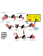

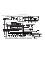
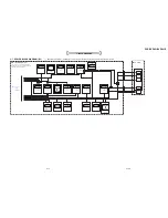
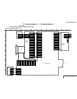

2. DISASSEMBLY
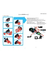
2. DISASSEMBLY
DCR-DVD201/DVD201E
2-3
2-4
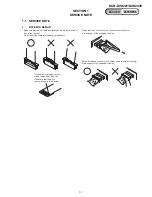
VC-354
VC-354
MD-104
MD-104
1
Screw (M1.7x2.5) silver
2
VC heat sink, VC radiation sheet,
VC insulating sheet
3
Screw (M1.7x2.5) silver
4
Claw
5
Screw (M1.7x2.5) silver
Screw
M1.7x3
3-084-817-21
Screw
M1.7x2.5
3-078-889-11
Silver
Black
Screw
M1.7x4
3-087-376-01
Tapping screw
M1.7x3.5
3-078-890-01
Tapping screw
M1.7x5
3-081-204-21
A
E
E
D
D
C
7
2
5
6
3
1
8
1
E
1
2
C
2
3
1
4
C
2
1
3
4
2
4
B
B
8
6
qa
5
3
0
4
D
D
D
1
C
B
D
E
7
3
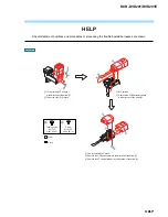
HELP 03
9
2
1
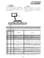
Three screws (M1.7x2.5) silver
2
Board to board (CN1007,CN4901) (100P)
3
Radiation sheet (135)
4
VC-354 board
1
Screw (M1.7x2.5) silver
2
VM heat sink, VM radiation sheet, VM insulating sheet
3
Tripod large
4
Sheet radiation (2345)
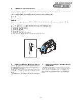
1
Two screws (M1.7x2.5) silver
2
Screw (M1.7x2.5) silver
3
Three tapping screws (M1.7x5) black
4
Tapping screw (M1.7x3.5) silver
1
Two tapping screws (M1.7x5) black
2
D blind plate assembly
1
Two tapping screws (M1.7x5) black
2
Tapping screw (M1.7x3.5) silver
3
Control switch block (PS8700)
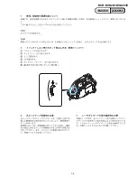
1
Remove the grip belt
in the direction of the arrow.
2
Two tapping screw (M1.7x3.5) silver
3
Grip belt sheet metal (Rear)
4
Grip belt
1
Open the jack cover (DC) in the directions of the arrows a and b.
2
DC-IN connector inlet
3
Harness (DM-144), FP-228 flexible board (Dew senser)
4
Control switch block (PS8700)
D
1
D
1
3
4
4
3
2
3
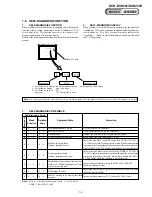
1
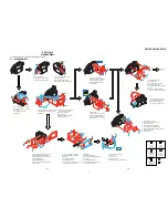
Remove the grip belt
in the direction of the arrow a.
2
Push this portion with a finger
in the direction of the arrow b.
3
Open the D lid assembly
in the direction of the arrow c.
5
DC-IN connector inlet (3P)
6
Harness (DM-144) (2P) (Dew sensor)
7
FP-891 flexible board (10P)
8
Remove the MD block assembly in the
direction of the arrow.
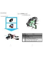
6
Two EG grip screws (M1.7x4) black
7
Control switch block (PS8700) (20P)
8
Battery terminal board (3P)
9
Battery terminal board
0
FP-887 flexible board (8P)
qa
Square type connector (USB 5P),
FP-887 flexible board
2
a
c
b
2
1
E
1
2
1
Two tapping screws (M1.7x5) black
2
Remove the D lid assembly
in the direction of the arrow.
Optical pickup
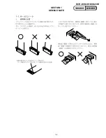
Caution
Precautions during handling
Refer to level 3
Disassembling procedure of
MD block assembly.
Be sure to place the DVD drive with its
optical pickup facing upward.
Do not touch the optical pickup surface.
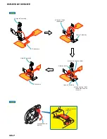
(J-2501-162-A)
Use the adjustable wrist strap (J-2501-162-A) as the
preventive measure for static electricity when the
removing and installing the MD black assembly because
the MD black assembly of this mechanism beck is easily
affected by the static electricity.
a
b
Summary of Contents for DCR-DVD201
Page 3: ... 3 DCR DVD201 DVD201E ENGLISH JAPANESE ENGLISH JAPANESE ...
Page 5: ... 5 DCR DVD201 DVD201E ENGLISH JAPANESE ENGLISH JAPANESE ...
Page 10: ...1 4 DCR DVD201 DVD201E ENGLISH JAPANESE ENGLISH JAPANESE SECTION 1 SERVICE NOTE ...
Page 11: ...1 5 DCR DVD201 DVD201E ENGLISH JAPANESE ENGLISH JAPANESE ...
Page 12: ...1 6E DCR DVD201 DVD201E ENGLISH JAPANESE ENGLISH JAPANESE ...
Page 18: ...Disassembling procedure of MD block assembly are not shown Page 2 10 is not shown ...
Page 65: ...5 13 DCR DVD201 DVD201E 5 REPAIR PARTS LIST 5 REPAIR PARTS LIST J MODEL ...


