— 4 —
DSC-W35_L2
TABLE OF CONTENTS
1.
SERVICE NOTE
1-1.
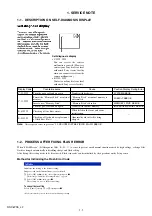
Description on Self-diagnosis Display ···························· 1-1
1-2.
Process After Fixing Flash Error ····································· 1-1
1-3.
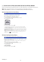
Method for Copying or Erasing the Data in Internal
Memory ··········································································· 1-2
1-4.
Precaution on Replacing the SY-175 Board ···················· 1-3
2.
DISASSEMBLY
2-1.
Disassembly ····································································· 2-2
2-2.
Exchange Method of Barrier Assy ·································· 2-6
2-3.
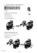
Exchange Method of Zoom Motor Unit ·························· 2-9
3.
BLOCK DIAGRAMS
3-1.
Overall Block Diagram (1/2) ··········································· 3-1
3-2.
Overall Block Diagram (2/2) ··········································· 3-2
3-3.
Power Block Diagram ····················································· 3-3
4.
PRINTED WIRING BOARDS AND
SCHEMATIC DIAGRAMS
4-1.
Frame Schematic Diagram ·············································· 4-1
4-2.
Schematic Diagrams ························································ 4-3
4-3.
Printed Wiring Boards ··················································· 4-16
4-4.
Mounted Parts Location ················································ 4-25
5.
REPAIR PARTS LIST
5-1.
Exploded Views ······························································· 5-2
5-2.
Electrical Parts List ························································· 5-6
Section
Title
Page


