33
CX-LEM550
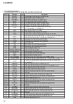
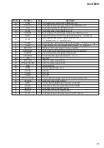
Pin No.
Pin Name
I/O
Description
73
TU CE
O
Chip enable signal output to the FM/AM tuner unit
74
TU CLOCK
O
Serial data transfer clock signal output to the FM/AM tuner unit
75
TU DI
I
Serial data input from the FM/AM tuner unit
76
TU DO
O
Serial data output to the FM/AM tuner unit
77
TU MUTE
O
Tuner muting on/off control signal output to the FM/AM tuner unit
78
TA MO
O
Capstan/reel motor on/off control signal output terminal “H”: motor on
79
TA RP
O
Recording/playback selection signal output terminal
“H”: playback mode, “L”: recording mode
80
TA BIAS
O
Recording bias on/off selection signal output terminal “H”: bias on, “L”: bias off
81
TA SOL
O
Trigger plunger on/off control signal output terminal “H”: plunger on
82
AMP-STBY
O
Standby control signal output to the power amplifier
83
AMP MUTE
O
Tuner muting on/off control signal output to the power amplifier
84
AU MUTE
O
Line muting on/off control signal output terminal
85
POWER ON
O
Power relay drive signal output terminal “H”: on
86
NC
—
Not used
87
ST-BY LED
O
LED drive signal output terminal
88
DSG/I-BASS LED
O
LED drive signal output terminal
89
VSS2
—
Ground terminal
90
VDD2
—
Power supply terminal (+3.1V)
91
CD LED
—
Not used
92
TU LED
—
Not used
93
TA LED
—
Not used
94
MD CD ON LED
O
Power on/off control signal output for the CD mechanism section
95
CD DATA
O
Serial data output to the CD DSP
96
SENS
I
Internal status (SENSE) signal input from the CD DSP
97
CD-CLK
O
Serial data transfer clock signal output to the CD DSP
98
MI-DIO-O
O
Serial data output to the MP3 decoder
99
MI-DIO-I
I
Serial data input from the MP3 decoder
100
MI-CK
O
Serial data transfer clock signal output to the MP3 decoder
Summary of Contents for CX-LEM550
Page 47: ...47 CX LEM550 MEMO ...

