

– 2 –
Specifications ........................................................................... 1
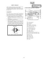
1. GENERAL
Location and Function of Controls .................................... 3
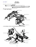
2. DISASSEMBLY
2-1. Cabinet (Rear) Removal ............................................. 4
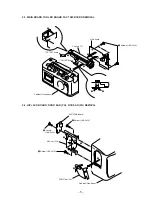
2-2. ISS SW Board, Battery Case,
BATTERY Board, POWER Board Removal ............. 4
2-3. Main Board, TUN LED Board,
TACT SW Board Removal ........................................ 5
2-4. H/P JACK Board, Door Ear (PH),
Box Ear (PH) Removal ............................................... 5
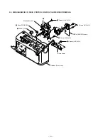
2-5. Mechanism Deck, DECK CONTROL Board
Volume Board Removal .............................................. 6
3. DIAL POINTER SETTING
......................................... 7
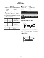
4. ADJUSTMENTS
4-1. Mechanical Adjustment .............................................. 8
4-2. Electrical Adjustment ................................................. 8
5. DIAGRAMS
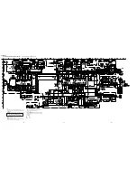
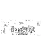
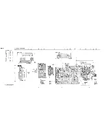
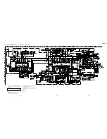
5-1. Schematic Diagram (AEP,UK Model) ...................... 12
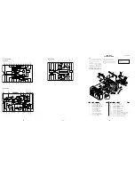
5-2. Printed Wiring Boards (AEP,UK Model) ................. 15
5-3. Printed Wiring Boards (US Model) .......................... 19
5-4. Schematic Diagram (US Model) .............................. 23
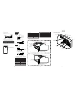
6. EXPLODED VIEWS
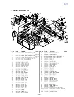
6-1. Cabinet (Rear) Section .............................................. 28
6-2. Cabinet (Front) Section ............................................ 29
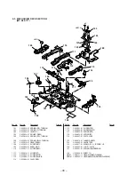
6-3. Mechanism Deck Section-1 (MF-A50-117) ............. 30
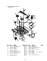
6-4. Mechanism Deck Section-2 (MF-A50-117) ............. 31
7. ELECTRICAL PARTS LIST
.................................... 32
SAFETY-RELATED COMPONENT WARNING!!
COMPONENTS IDENTIFIED BY MARK
!
OR DOTTED LINE WITH
MARK
!
ON THE SCHEMATIC DIAGRAMS AND IN THE PARTS
LIST ARE CRITICAL TO SAFE OPERATION.
REPLACE THESE COMPONENTS WITH SONY PARTS WHOSE
PART NUMBERS APPEAR AS SHOWN IN THIS MANUAL OR IN
SUPPLEMENTS PUBLISHED BY SONY.
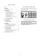
TABLE OF CONTENTS
HOW TO CHANGED THE CERAMIC FILTERS
This model is used three ceramic filters of CF2, CF4 and CF3.
You must used same type of color marked ceramic filters in order
to meet same specifications.
Therefore, the ceramic filter must changed three pieces together
since it's supply three pieces in one package as a spare parts.
Mark
Center
fequency
red
blue
orange
black
white
10.70MHz
10.67MHz
10.73MHz
10.64MHz
10.76MHz
mark
mark
CF2, 4
CF3