background image

48

CDX-R5515X/R5610/R6550

SECTION 5

ELECTRICAL PARTS LIST

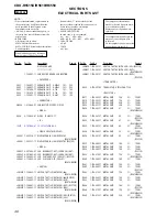
NOTE:

• Due to standardization, replacements in

the parts list may be different from the
parts specified in the diagrams or the
components used on the set.

• -XX and -X mean standardized parts, so

they may have some difference from the
original one.

• RESISTORS

All resistors are in ohms.
METAL:Metal-film resistor.
METAL OXIDE: Metal oxide-film resistor.
F:nonflammable

• Items marked “*” are not stocked since

they are seldom required for routine service.
Some delay should be anticipated
when ordering these items.

• SEMICONDUCTORS

In each case, u : 

µ

, for example:

uA.. : 

µ

A..

uPA.. : 

µ

PA..

uPB.. : 

µ

PB.. uPC..: 

µ

PC.. uPD.. : 

µ

PD..

• CAPACITORS

uF : 

µ

F

• COILS

uH : 

µ

H

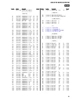
Ref. No.

Part No.

Description

Remark

Ref. No.

Part No.

Description

Remark

The components identified by
mark 

0

 or dotted line with mark

0

 are critical for safety.

Replace only with part number
specified.

Les composants identifiés par une
marque 

0

 sont critiques pour

la sécurité.
Ne les remplacer que par une piéce
portant le numéro spécifié.

When indicating parts by reference
number, please include the board.

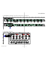
DISPLAY BOARD

**************

1-780-201-11 CONDUCTIVE BOARD, CONNECTION

< CAPACITOR >

C981

1-164-227-11 CERAMIC CHIP

0.022uF

10%

25V

C982

1-164-227-11 CERAMIC CHIP

0.022uF

10%

25V

C983

1-107-826-11 CERAMIC CHIP

0.1uF

10%

16V

C984

1-107-826-11 CERAMIC CHIP

0.1uF

10%

16V

C985

1-125-891-11 CERAMIC CHIP

0.47uF

10%

10V

< CONNECTOR >

CN904

1-818-969-21 CONNECTOR, FFC/FPC (ZIF) 12P

< DIODE >

D984

8-719-988-61 DIODE   1SS355TE-17

< IC >

IC901

6-707-064-01 IC   LC75876WH-US-E

< LIQUID CRYSTAL DISPLAY >

LCD901 1-805-736-11 DISPLAY PANEL, LIQUID CRYSTAL

(R5610/R6550)

LCD901 1-805-737-11 DISPLAY PANEL, LIQUID CRYSTAL (R5515X)

< DIODE >

LED931 6-501-062-01 LED   NSCW505CT-AST (LCD BACK LIGHT)
LED932 6-501-062-01 LED   NSCW505CT-AST (LCD BACK LIGHT)
LED961 6-500-895-01 LED   CL-270UB2-X-TS (CD SLOT) (R5515X)
LED961 8-719-082-38 LED   CL-270SR-C-TS (CD SLOT)

(R5610/R6550)

< SWITCH >

LSW901 1-786-805-11 SWITCH, TACTILE (WITH LED) (

Z

)

(R5610/R6550)

LSW901 1-786-807-11 SWITCH, TACTILE (WITH LED) (

Z

) (R5515X)

LSW918 1-786-805-11 SWITCH, TACTILE (WITH LED) (DSO)

(R5610/R6550)

LSW918 1-786-807-11 SWITCH, TACTILE (WITH LED) (DSO) (R5515X)
LSW919 1-786-805-11 SWITCH, TACTILE (WITH LED) (EQ3)

(R5610/R6550)

LSW919 1-786-807-11 SWITCH, TACTILE (WITH LED) (EQ3)(R5515X)
LSW920 1-786-805-11 SWITCH, TACTILE (WITH LED) (SEL)

(R5610/R6550)

LSW920 1-786-807-11 SWITCH, TACTILE (WITH LED) (SEL) (R5515X)
LSW921 1-786-805-11 SWITCH, TACTILE (WITH LED) (DSPL)

(R5610/R6550)

LSW921 1-786-807-11 SWITCH, TACTILE (WITH LED) (DSPL)

(R5515X)

< TRANSISTOR >

Q925

8-729-027-58 TRANSISTOR   DTC143ZKA-T146

< RESISTOR >

R917

1-216-823-11 METAL CHIP

1.5K

5%

1/10W

R918

1-216-823-11 METAL CHIP

1.5K

5%

1/10W

R919

1-216-825-11 METAL CHIP

2.2K

5%

1/10W

R920

1-216-827-11 METAL CHIP

3.3K

5%

1/10W

R924

1-216-805-11 METAL CHIP

47

5%

1/10W

(R5610/R6550)

R924

1-216-807-11 METAL CHIP

68

5%

1/10W

(R5515X)

R925

1-216-805-11 METAL CHIP

47

5%

1/10W

(R5610/R6550)

R925

1-216-807-11 METAL CHIP

68

5%

1/10W

(R5515X)

R926

1-216-804-11 METAL CHIP

39

5%

1/10W

(R5610/R6550)

R926

1-216-807-11 METAL CHIP

68

5%

1/10W

(R5515X)

R953

1-216-809-11 METAL CHIP

100

5%

1/10W

R954

1-216-809-11 METAL CHIP

100

5%

1/10W

R955

1-216-809-11 METAL CHIP

100

5%

1/10W

(R5515X)

R955

1-216-810-11 METAL CHIP

120

5%

1/10W

(R5610/R6550)

R960

1-216-809-11 METAL CHIP

100

5%

1/10W

R961

1-216-809-11 METAL CHIP

100

5%

1/10W

R962

1-216-809-11 METAL CHIP

100

5%

1/10W

(R5515X)

R962

1-216-810-11 METAL CHIP

120

5%

1/10W

(R5610/R6550)

R964

1-216-809-11 METAL CHIP

100

5%

1/10W

R965

1-216-809-11 METAL CHIP

100

5%

1/10W

R966

1-216-809-11 METAL CHIP

100

5%

1/10W

(R5515X)

R966

1-216-810-11 METAL CHIP

120

5%

1/10W

(R5610/R6550)

R969

1-216-815-11 METAL CHIP

330

5%

1/10W

(R5610/R6550)

DISPLAY

Summary of Contents for CDX-R5515X - Fm/am Compact Disc Player

Page 1: ...tion at 1 kHz 0 5 stereo 0 3 mono Separation 35 dB at 1 kHz Frequency response 30 15 000 Hz AM CDX R5515X Tuning range 530 1 710 kHz Antenna terminal External antenna connector Intermediate frequency 10 7 MHz 450 kHz Sensitivity 30 µV SPECIFICATIONS AM CDX R5610 Tuning range 531 1 602 kHz at 9 kHz step 530 1 710 kHz at 10 kHz step AM tuning interval 9 kHz 10 kHz switchable Aerial terminal External...

Page 2: ...cted to a digital preamplifier or an equalizer which is Sony BUS system compatible Design and specifications are subject to change without notice SERVICE NOTES NOTES ON HANDLING THE OPTICAL PICK UP BLOCK OR BASE UNIT The laser diode in the optical pick up block may suffer electrostatic breakdown because of the potential difference generated by the charged electrostatic load etc on clothing and the...

Page 3: ...me printed circuit boards may not come printed with the lead free mark due to their particular size LEAD FREE MARK Unleaded solder has the following characteristics Unleaded solder melts at a temperature about 40 C higher than ordinary solder Ordinary soldering irons can be used but the iron tip has to be applied to the solder joint for a slightly longer time Soldering irons using a temperature re...

Page 4: ...n 24 3 5 Printed Wiring Boards CD Mechanism Section 25 3 6 Schematic Diagram CD Mechanism Section 1 2 26 3 7 Schematic Diagram CD Mechanism Section 2 2 27 3 8 Printed Wiring Board Main Section 28 3 9 Schematic Diagram Main Section 1 2 29 3 10 Schematic Diagram Main Section 2 2 30 3 11 Printed Wiring Board Key Section 31 3 12 Schematic Diagram Key Section 32 3 13 Printed Wiring Board Display Sectio...

Page 5: ...lace the battery see Replacing the lithium battery of the card remote commander on page 14 6 Location of controls and basic operations Main unit OPEN CLOSE shutter opened Card remote commander RM X151 Refer to the pages listed for details The corresponding buttons on the card remote commander control the same functions as those on the unit A Volume button To adjust volume B ATT attenuate button To...

Page 6: ...encies TA Traffic Announcement button 9 To set AF and TA TP in RDS P SENS BTM button 8 To improve weak reception LOCAL MONO press start the BTM function press and hold Q PTY Programme Type LIST button 10 To select PTY in RDS list up R Receptor for the card remote commander S Disc slot 5 T Z eject button 5 The following buttons on the card remote commander have also different buttons functions from...

Page 7: ...mehr CD MD Wechslern wird der gesondert erhältliche Signalquellenwähler XA C30 benötigt Exemple de raccordement 2 Remarques 2 A Raccordez d abord le câble de mise à la masse avant de connecter l amplificateur L alarme est émise uniquement lorsque l amplificateur intégré est utilisé Conseil 2 B Dans le cas du raccordement de deux changeurs de CD MD ou plus le sélecteur de source XA C30 en option es...

Page 8: ...t speakers with those of the left speaker Do not connect the ground lead of this unit to the negative terminal of the speaker Do not attempt to connect the speakers in parallel Connect only passive speakers Connecting active speakers with built in amplifiers to the speaker terminals may damage the unit To avoid a malfunction do not use the built in speaker leads installed in your car if the unit s...

Page 9: ...9 CDX R5515X R5610 R6550 CDX R5610 ...

Page 10: ...io dell auto e non collegare i terminali del diffusore destro a quelli del diffusore sinistro Non collegare il cavo di terra di questo apparecchio al terminale negativo del diffusore Non collegare i diffusori in parallelo Assicurarsi di collegare soltanto diffusori passivi poiché il collegamento di diffusori attivi dotati di amplificatori incorporati ai terminali dei diffusori potrebbe danneggiare...

Page 11: ...T FRONT PANEL COMPLETE ASSY 2 11 FRONT BACK PANEL LCD Page 17 2 12 KEY BOARD Page 17 2 13 DISPLAY SECTION Page 18 2 14 SPRING M Page 18 2 15 SPRING S Page 19 2 3 MAIN BOARD Page 13 2 4 CHASSIS T SUB ASSY Page 13 2 5 ROLLER ARM ASSY Page 14 2 6 CHASSIS OP ASSY Page 14 2 8 SL MOTOR ASSY M902 Page 15 2 10 SERVO BOARD Page 16 2 7 OPTICAL PICK UP Page 15 2 9 LE MOTOR ASSY M903 Page 16 ...

Page 12: ...ow the disassembly procedure in the numerical order given 2 1 SUB PANEL LCD ASSY 2 two claws 3 two claws 4 sub panel LCD assy 1 two screws PTT 2 6 x 6 7 bracket CD 5 CD mechanism block 4 CN350 3 1 screw PTT 2 6 x 6 2 screw PTT 2 6 x 6 6 two screws PTT 2 6 x 4 ...

Page 13: ... R6550 2 4 CHASSIS T SUB ASSY 2 3 MAIN BOARD 1 three screws BTT 3 MAIN board 4 insulating sheet 2 two screws PTT 2 6 x 8 5 SENSOR board 6 chassis T sub assy 4 claw 3 claw 1 two screws P 1 7 x 2 2 2 two screws P 1 7 x 2 2 ...

Page 14: ...IS OP ASSY 3 washer 1 1 2 5 4 gear RA1 5 roller arm assy 1 spring RAL 2 spring RAR 4 washer 0 coil spring damper 9 two coil springs damper qa chassis OP assy 5 gear LE1 1 CN2 16P lever D slider R 6 7 8 2 Remove the six solderings 3 tension coil spring KF60 ...

Page 15: ...X R5610 R6550 2 7 OPTICAL PICK UP 2 8 SL MOTOR ASSY M902 1 tension coil spring CHKG 2 chucking arm sub assy 3 screw B 1 4 x 5 4 rack SL 5 claw 6 main shaft 7 optical pick up 1 screw P 1 4 x 1 8 2 SL motor assy M902 ...

Page 16: ...t LEM N slider R 6 screw P 1 7 x 2 2 8 screw M 1 7 x 2 5 qa screw M 1 7 x 2 5 qf two toothed lock screws M 1 4 qs screw M 1 7 x 2 5 9 bearing LEB N 0 gear LE assy qg LE motor assy M903 1 Remove the soldering 3 CN2 16P 5 claw 6 SERVO board 4 toothed lock screw M 1 7 1 Remove the eight solderings 2 Remove the three solderings ...

Page 17: ...X R5515X R5610 R6550 2 11 FRONT BACK PANEL LCD 2 12 KEY BOARD 1 two screws P 2 x 8 3 front back panel LCD three claws three claws two claws two claws 2 two screws P 2 x 8 1 2 CN903 6P 3 CN902 12P 4 KEY board ...

Page 18: ...n the arrowed direction Note for assembly After installing to the front panel assy make sure the spring is not off from the dowel Note for assembly After installing to the front panel assy make sure the spring is not off from the dowel 4 display section front panel assy 3 1 spring M 2 spring M 3 bracket display ...

Page 19: ... side 3 Take off the spring from the dowel on preset assy side preset assy Make sure the spring is not off from the dowel Make sure the spring is not off from the dowel preset assy display SV assy display SV assy Put preset assy back in the arrowed direction display SV assy Note for assembly 1 Raise the preset assy up in the arrowed direction ...

Page 20: ...20 CDX R5515X R5610 R6550 MEMO ...

Page 21: ...27 RO R CH 27 DEC SSTBY 15 CD ZDET 14 CD XRST 13 CD XCCE 53 MEC_SELFSW 45 MEC_INSW 42 MEC_LIMIT 12 CD BUCK 11 CD BUS3 38 BUS2 10 CD BUS2 37 BUS1 8 CD BUS1 36 BUS0 7 CD BUS0 14 SBSY 52 CD SBSY 81 X1 80 X0 MEC LOAD 43 MEC EJECT 44 CD SYSTEM CONTROL IC3 1 5V REG IC6 SYSTEM CONTROL IC501 1 3 37 DEC XMUTE 30 DEC INT SW2 SELF 46 MEC_DSW SW1 DOWN SW3 DISC IN SW4 LIMIT 56 60 UNISI A ATT 25 RXD 57 UNISO 58...

Page 22: ...T 17 18 OUT RF OUT RR1 21 MUTE 2 SDA AUDIO 8 3V BU 5V SERVO 3 3V MECHA 6V PANEL B 4 SCL SDA SCL 16 BEEP 22 STB 25 DIAG AUDIO 8 3V 35 VP 20 VP1 6 VP2 15 7 10 12 11 16 1 9 2 4 3 5 6 22 23 SCL SDA SCL SDA SCL SDA SCL SDA 33 I2C CKO 34 I2C SIO 9 VOL ATT 86 ATT 5 BEEP 26 AMP STB 8 DIAG 75 ILLUMI 73 30 ATT 56 TEST IN 12 IN FL FL FL RL RL FR FR RR RR AMP REM ANT REM ACC TEST NC 20 OUT LF 11 IN RL 19 OUT ...

Page 23: ...DISPLAY PANEL D501 1 2 D501 2 2 D400 KEY BOARD 65 68 S1 S48 CL DI NC1 NC2 CE 64 SIRCS 70 SYNCHRO SW IR LED902 914 918 LSW903 913 918 921 Q925 LED CONTROL S501 FREQUENCY SELECT LED931 932 PANEL B BU 3 3V R5610 ONLY IR RECEIVER IC972 PANEL B LED961 LSW901 S961 NOSE DET 2 OUT BU 3 3V KEY MATRIX RESET IC602 LSW903 913 918 921 S902 914 918 VDD VOUT LCD BACK LIGHT CD SECTION C 10 3 B U CHECK BATT BATT C...

Page 24: ...nces Waveforms are taken with a oscilloscope Voltage variations may be noted due to normal produc tion tolerances Circled numbers refer to waveforms Signal path J CD PLAY F FM f AM MW LW Caution Pattern face side Parts on the pattern face side seen from the Side B pattern face are indicated Parts face side Parts on the parts face side seen from the Side A parts face are indicated Q C These are omi...

Page 25: ...P22 TP68 TP93 TP15 TP64 FMB3 FMB4 TP11 TP86 TP87 TP10 TP1 TP6 TP7 TP8 TP9 TP12 TP13 TP16 TP20 TP32 TP31 TP66 TP67 TP74 TP75 TP76 TP77 TP78 TP79 TP80 TP81 TP82 TP83 TP84 TP85 TP90 TP89 TP88 TP91 TP92 TP95 TP97 TP98 TP99 TP2 TP63 TP44 TP43 TP65 TP62 F M B 5 TP101 TP23 TP29 C N 1 R4 R24 R5 CN2 R61 C5 R49 R51 R45 R46 R2 R3 X1 X1 IC2 R121 C10 C4 R119 C18 C47 C34 R118 C17 C23 C42 C16 C60 R125 C36 R62 R1...

Page 26: ...1 R25 R41 TP42 TP20 TP21 TP22 TP25 TP18 TP17 TP29 R23 R21 R24 TP93 TP101 R49 C58 C59 R131 R113 C5 C27 C23 C20 C19 C17 C18 C21 C29 C35 C32 C33 C72 C80 Q3 C102 C53 C51 C49 C57 C48 C42 FB2 FB3 C67 C60 R52 C52 C47 C16 C13 C31 R19 R46 R45 FB4 R123 C36 R132 R5 R4 R51 R112 Q1 C9 IC6 R13 IC2 R1 C10 X2 C4 C24 C28 C22 C7 C101 C45 TP12 TP13 TP16 TP15 TP14 R64 R62 R63 R61 R60 R59 C62 R125 R126 R127 R128 C34 C...

Page 27: ... R73 R69 R53 R11 R10 R8 R9 R70 TP1 TP2 TP3 TP4 TP5 TP43 TP67 TP66 R116 R118 R119 R121 C106 C37 R78 R77 R91 R90 R80 R117 R122 R42 R43 R74 R17 R16 C6 R100 R101 IC1 CN2 R12 SW4 SW1 SW3 SW2 M903 M901 M902 R2 R3 R120 C105 R28 X1 C103 IC3 C43 C64 C65 TP74 TP75 TP76 TP77 TP78 TP79 TP80 TP81 TP82 TP83 TP84 TP85 TP86 TP87 TP10 TP11 TP7 TP6 TP9 TP8 TP32 TP31 TP23 TP24 R58 R48 R50 R54 R56 R66 R68 R81 R82 R83...

Page 28: ...523 R524 R517 R518 JC507 R57 C511 C510 C512 R371 C513 R521 R539 C329 C519 R533 R527 FMB3 FMB4 Q600 JC998 L1 C362 C361 R551 L500 L4 R553 C14 R554 C62 IC501 D400 D493 D511 R103 R104 R105 R400 L400 L401 C303 C441 C451 C461 C431 C471 C421 C486 R450 C365 C367 C480 C481 C1 C2 C5 C310 C308 C306 C314 C316 D308 D307 D305 D306 D311 D310 D312 D309 D302 D301 D304 D303 D607 C701 L300 CNJ400 CN300 TH400 C600 R7...

Page 29: ...511 Q491 C601 C329 C502 C318 C319 JC300 JC301 C323 C301 JC302 C304 C305 C307 C324 C309 C472 C462 C484 JC513 JC490 JC491 C442 C422 C452 C432 C413 C414 JC430 C362 C361 C483 C481 C480 L3 L2 R55 R54 C423 C8 R6 R7 C7 C9 C3 R601 JC601 D607 C701 L300 C704 R712 C703 D705 R711 R702 R707 R603 D603 D602 R604 R608 R611 R607 R606 C901 D703 D704 D702 D701 C902 R701 R710 R705 R709 C501 C310 C320 C312 C313 C314 C...

Page 30: ...00 R528 R516 L500 R553 R518 D400 D493 L400 C403 R401 R402 R102 FB404 FB407 FB408 C417 C412 FB401 C419 C418 C402 C506 JC350 C515 JC508 JC506 JC507 C504 C507 C510 C511 JC511 JC512 JC509 JC502 JC501 JC503 X501 R551 C519 FB403 C415 R351 C513 C514 C512 R371 R520 R554 S501 R527 R525 R526 J370 C505 D502 R547 IC602 Q501 R507 R508 S103 CN101 C508 R549 R548 L401 C516 X500 IC501 R550 R538 JC510 R541 C509 C50...

Page 31: ... R5515X R5610 R6550 R5515X R5610 R6550 R5515X LED916 LED917 LED918 R901 R948 R949 S914 S915 S961 12 1 S961 NOSE DET R902 IC972 IC972 CN903 FMB3 CN902 FMB4 D903 D962 D963 D906 D902 R976 R913 R914 R915 R916 JP942 R950 R973 R974 R951 R952 R975 C973 R990 CN901 D981 3 11 PRINTED WIRING BOARD KEY SECTION Refer to page 24 for Circuit Boards Location Uses unleaded solder Page 35 Page 33 Page 28 Ref No Loc...

Page 32: ...ION R972 R913 R914 R915 R916 S961 CN902 CN903 D962 D902 D903 D963 CN901 D906 C973 R975 R976 D981 R990 R901 R902 IC972 LED902 LED914 LED917 LED915 JP942 R949 R944 R950 JP941 R945 LED918 LED916 R951 R946 R952 R947 R973 R974 R948 R943 S902 S914 S915 S916 S917 S918 Page 34 Page 35 Page 30 ...

Page 33: ...7 R918 R919 R920 LED932 LED931 LSW921 LSW921 LSW920 LSW901 LSW901 LSW918 DSO EQ3 DSPL SEL LED931 LCD BACK LIGHT LED932 LCD BACK LIGHT LSW918 LSW919 R961 R960 R962 R983 C981 C982 C983 C984 C985 R987 R924 R925 R926 R964 R965 R966 IC901 LED961 D984 Q925 R980 R982 R981 LMB3 LMB4 LMB5 LMB6 CN904 12 1 R969 LCD911 LIQUID CRYSTAL DISPLAY PANEL 1 72 36 37 LED961 CD SLOT Page 31 Ref No Location D984 F 5 IC9...

Page 34: ...R982 R980 R981 R917 R918 R919 R920 R953 R960 R964 Q925 CN904 C981 C982 C984 C983 R983 D984 LCD911 LED931 LSW921 2 2 LSW918 2 2 LED932 LSW920 2 2 LSW919 2 2 LSW901 2 2 LSW901 1 2 LSW918 1 2 LSW919 1 2 LSW920 1 2 LSW921 1 2 IC901 LED961 R966 R962 R955 R924 R925 R926 R969 R965 R961 R954 C985 Page 32 ...

Page 35: ...907 1 2 LSW908 1 2 LSW905 1 2 LSW906 1 2 LSW909 1 2 LSW910 1 2 LSW911 1 2 LSW912 1 2 LSW913 1 2 LSW903 2 2 LSW907 2 2 LSW911 2 2 LSW905 2 2 LSW909 2 2 LSW913 2 2 1 A B C D 2 3 4 5 6 7 8 9 10 11 12 13 14 D KEY BOARD CN903 1 864 699 11 1 864 699 11 LSW903 LSW905 LSW906 LSW907 LSW908 LSW909 LSW910 LSW911 LSW912 LSW913 PTY LIST SENS BTM AF TA 6 5 BBE MP 4 SHUF 3 REP 2 GP DISC 1 LSW904 MODE SOURCE LSW9...

Page 36: ...VOUT NC 4 IC1 BA5968FP E2 SERVO Board 2 2 1 2 11 13 14 12 LEVEL SHIFT LEVEL SHIFT LEVEL SHIFT LEVEL SHIFT MUTE FWD FWD LDCTL NC OPOUT1 NC NC OPOUT2 POWVCC VCC VOL VOL VOL2 VOL2 VO1 VO1 REV OPIN4 OPIN4 OPOUT4 OPIN3 OPIN3 OPOUT3 MUTE VOL GND VOL3 VOL3 VOL4 VOL4 REV OUTR OUTF 10 9 8 7 6 5 28 27 26 25 24 23 22 21 20 19 18 17 16 15 4 3 IC50 TDA7333013TR MAIN Board 1 2 VDDA INTERPOLATOR RAM BUFFER CONTR...

Page 37: ... SOFTSEP MONO FADER SUBWOOFER L P F MIX MIX HPF BUSS MIDDLE SPECTRUM ANALYZER TREBLE SOFTSTEP VOLUME IN GAIN AUTO ZERO SOFT MUTE LOUDNESS HPF SOFTSEP MONO FADER SOFTSEP MONO FADER SOFTSEP MONO FADER ACOUTR ACINR ACINL ACOUTL AC2INL AC2INR SE2L SE2R SE1L SE1R DIFFL DIFFG DIFFR CREF GND OUTLR2 OUTRF OUTRR1 OUTLR1 OUTLF MUTE SCL SDA VDD SAIN SAOUT VREF OUTRR2 IC401 TDA7419TR MAIN Board 1 2 ...

Page 38: ...e voltage for A D converter 35 AVSS Ground pin 36 NC Not used Open 37 DEC XMUTE O Mute signal output L mute 38 39 NC Not used Open 40 VSS Ground pin 41 NC Not used Open 42 MEC LIMIT I Sled limit in detection switch signal input 43 MEC LOAD O Loading motor signal output Load direction 44 MEC EJECT O Loading motor signal output Eject direction 45 MEC INSW I Pack in detection signal input 46 MEC DSW ...

Page 39: ...put 76 NC Not used Open 77 X1A Sub clock connect pin Not used in this set Open 78 X0A Sub clock connect pin Not used in this set Connect to Vss 79 VSS Ground pin 80 X0 I Main clock connect pin 12 MHz 81 X1 O Main clock connect pin 12 MHz 82 VCC Power supply pin 3 3 V 83 XTS I Not used in this set Open 84 XINIT3 I Not used in this set Open 85 NC Not used Open 86 XSJIG I Not used in this set Open 87...

Page 40: ... EEPROM bus serial data input output 25 EEP CKO O EEPROM bus serial clock output 26 AMP STB O Power AMP satandby signal output 27 LCD CE O LCD driver chip enable output 28 LCD SO O LCD driver serial data output 29 LCD SCK O LCD driver serial clock output 30 RDS ON O RDS ON signal output 31 NCO O Not used 32 NCO O Not used 33 I2C SCK O I2C bus serial clock output 34 I2C SIO I O I2C bus serial data ...

Page 41: ...detect signal input 73 TEST IN I Test mode detect signal input 74 TEL ATT I Telephone attenuate detect signal input 75 ILLU IN I Illumination detect signal input 76 XKEY ON O A D converter power supply control signal output 77 RESET I CPU reset input 78 NCO O Not used 79 XIN Sub clock input 32 768kHz 80 XOUT Sub clock output 32 768kHz 81 VSS1 Ground 82 OSC IN Main clock input 3 68MHz 83 OSC OUT Ma...

Page 42: ...y have some difference from the original one Color Indication of Appearance Parts Example KNOB BALANCE WHITE RED Parts Color Cabinet s Color Accessories are given in the last of this parts list R R 1 X 2023 967 1 PANEL LCD ASSY SUB 2 2 583 939 01 SCREW B 2X4 3 X 2024 365 1 LOCK ASSY S 4 3 246 006 31 COVER 5 2 583 940 01 SCREW BTT 6 1 776 207 72 CORD WITH CONNECTOR POWER R5515X R5610 6 1 776 527 71...

Page 43: ...IGHT GUIDE 63 2 187 154 11 SPRING M 64 2 187 132 01 BRACKET DISPLAY 65 2 187 154 01 SPRING M 66 2 187 127 01 PANEL LCD FRONT BACK 67 1 780 201 11 CONDUCTIVE BOARD CONNECTION 68 1 830 259 11 CABLE FLEXIBLE FLAT 12 CORE 69 2 187 139 01 COVER PWB 70 X 2050 189 1 CASE ASSY for FRONT PANEL 71 A 1084 642 A PANEL COMPLETE ASSY FRONT R6550 71 A 1085 704 A PANEL COMPLETE ASSY FRONT R5610 71 A 1085 925 A PA...

Page 44: ...LTR TENSION COIL 103 3 253 746 14 SPRING DAMPER COMPRESSION 104 3 253 746 03 SPRING DAMPER COMPRESSION 105 2 345 767 01 SPRING KF60 TENSION 106 3 253 748 01 DAMPER S 107 3 352 758 31 SCREW M1 7 TOOTHED LOCK 108 A 1075 784 A SERVO BOARD COMPLETE 5 7 627 552 87 SCREW PRECISION P 1 7X2 2 not supplied SENSOR board not supplied not supplied not supplied not supplied 5 101 102 103 104 105 106 107 108 ...

Page 45: ... LEVER SL SUB ASSY 157 X 3383 454 3 LEVER SL ASSY 158 3 261 959 02 SPRING SL TORSION M902 A 3337 638 A MOTOR ASSY SL SLED SW4 1 571 099 11 SWITCH 1 KEY LIMIT 6 7 627 850 77 SCREW PRECISION P 1 4X1 8 The components identified by mark 0 or dotted line with mark 0 are critical for safety Replace only with part number specified Les composants identifiés par une marque 0 sont critiques pour la sécurité...

Page 46: ...A ARM ASSY ROLLER 204 3 259 455 02 SPRING RAL 205 3 253 713 01 SPRING RAR 206 3 259 469 01 SPRING LE LEAF 207 2 134 636 31 SCREW M1 7X2 5 208 2 186 696 11 BRACKET LEM N 209 3 345 648 91 SCREW M1 4 TOOTHED LOCK 210 A 1083 637 A GEAR LE ASSY 211 2 186 697 11 BEARING LEB N M903 A 1075 792 A MOTOR ASSY LE LOADING 5 7 627 552 87 SCREW PRECISION P 1 7X2 2 5 M903 208 210 211 209 207 207 207 201 202 203 2...

Page 47: ...iption Remark 4 6 CD MECHANISM SECTION 4 MG 611TA 186 K 251 2 186 700 11 GEAR CHK1 252 3 344 223 01 WASHER 253 3 259 470 01 GEAR LE1 254 3 253 755 02 LEVER D 255 3 899 829 01 WASHER SLIT 256 3 259 032 01 GEAR LE2 257 A 1075 791 A CHASSIS M BLOCK ASSY 251 252 252 254 255 256 257 253 ...

Page 48: ...HT LED932 6 501 062 01 LED NSCW505CT AST LCD BACK LIGHT LED961 6 500 895 01 LED CL 270UB2 X TS CD SLOT R5515X LED961 8 719 082 38 LED CL 270SR C TS CD SLOT R5610 R6550 SWITCH LSW901 1 786 805 11 SWITCH TACTILE WITH LED Z R5610 R6550 LSW901 1 786 807 11 SWITCH TACTILE WITH LED Z R5515X LSW918 1 786 805 11 SWITCH TACTILE WITH LED DSO R5610 R6550 LSW918 1 786 807 11 SWITCH TACTILE WITH LED DSO R5515X...

Page 49: ...5SR CD T SEEK m R5610 R6550 RESISTOR R901 1 216 819 11 METAL CHIP 680 5 1 10W R902 1 216 819 11 METAL CHIP 680 5 1 10W R913 1 216 819 11 METAL CHIP 680 5 1 10W R914 1 216 819 11 METAL CHIP 680 5 1 10W R915 1 216 819 11 METAL CHIP 680 5 1 10W R916 1 216 821 11 METAL CHIP 1K 5 1 10W R943 1 216 809 11 METAL CHIP 100 5 1 10W R5610 R6550 R943 1 216 811 11 METAL CHIP 150 5 1 10W R5515X R944 1 216 811 11...

Page 50: ... C314 1 126 964 11 ELECT 10uF 20 50V C315 1 162 970 11 CERAMIC CHIP 0 01uF 10 25V C316 1 104 665 11 ELECT 100uF 20 25V C317 1 126 961 11 ELECT 2 2uF 20 50V C318 1 162 923 11 CERAMIC CHIP 47PF 5 50V C319 1 127 715 11 CERAMIC CHIP 0 22uF 10 16V C320 1 162 970 11 CERAMIC CHIP 0 01uF 10 25V C323 1 115 340 11 CERAMIC CHIP 0 22uF 10 25V C324 1 115 340 11 CERAMIC CHIP 0 22uF 10 25V C329 1 165 319 11 CERA...

Page 51: ... 1 580 907 41 PLUG CONNECTOR BUS CONTROL IN DIODE D2 8 719 069 55 DIODE UDZSTE 175 6B D101 6 500 886 01 DIODE RSA6 1ENTR D102 6 500 886 01 DIODE RSA6 1ENTR D301 6 500 522 01 DIODE 10EDB40 TA1B2 D302 6 500 522 01 DIODE 10EDB40 TA1B2 D303 6 500 522 01 DIODE 10EDB40 TA1B2 D304 6 500 522 01 DIODE 10EDB40 TA1B2 D305 6 500 522 01 DIODE 10EDB40 TA1B2 D306 6 500 522 01 DIODE 10EDB40 TA1B2 D307 6 500 522 0...

Page 52: ...TC114EKA T146 Q701 8 729 120 28 TRANSISTOR 2SC1623 L5L6 Q702 8 729 120 28 TRANSISTOR 2SC1623 L5L6 Q703 8 729 120 28 TRANSISTOR 2SC1623 L5L6 RESISTOR R1 1 216 809 11 METAL CHIP 100 5 1 10W R6550 R2 1 216 839 11 METAL CHIP 33K 5 1 10W R6550 R3 1 216 843 11 METAL CHIP 68K 5 1 10W R6550 R4 1 216 839 11 METAL CHIP 33K 5 1 10W R5 1 216 843 11 METAL CHIP 68K 5 1 10W R6 1 414 595 11 INDUCTOR FERRITE BEAD ...

Page 53: ... 10W R531 1 216 845 11 METAL CHIP 100K 5 1 10W R532 1 216 845 11 METAL CHIP 100K 5 1 10W R533 1 216 845 11 METAL CHIP 100K 5 1 10W R534 1 216 845 11 METAL CHIP 100K 5 1 10W R535 1 216 864 11 SHORT CHIP 0 R536 1 216 864 11 SHORT CHIP 0 R537 1 216 845 11 METAL CHIP 100K 5 1 10W R538 1 216 864 11 SHORT CHIP 0 R5515X R5610 R539 1 216 809 11 METAL CHIP 100 5 1 10W R540 1 216 809 11 METAL CHIP 100 5 1 1...

Page 54: ... 1 10W R905 1 216 823 11 METAL CHIP 1 5K 5 1 10W R906 1 216 823 11 METAL CHIP 1 5K 5 1 10W R907 1 216 825 11 METAL CHIP 2 2K 5 1 10W Ref No Part No Description Remark R908 1 216 827 11 METAL CHIP 3 3K 5 1 10W R909 1 216 829 11 METAL CHIP 4 7K 5 1 10W R910 1 218 867 11 METAL CHIP 6 8K 0 5 1 10W R911 1 216 833 11 METAL CHIP 10K 5 1 10W R912 1 216 835 11 METAL CHIP 15K 5 1 10W R930 1 216 813 11 METAL...

Page 55: ...67 81 CERAMIC CHIP 0 01uF 10 25V C67 1 125 837 11 CERAMIC CHIP 1uF 10 6 3V C72 1 125 837 11 CERAMIC CHIP 1uF 10 6 3V C80 1 125 837 11 CERAMIC CHIP 1uF 10 6 3V C101 1 100 567 81 CERAMIC CHIP 0 01uF 10 25V C102 1 162 962 11 CERAMIC CHIP 470PF 10 50V C103 1 100 567 81 CERAMIC CHIP 0 01uF 10 25V C105 1 125 777 11 CERAMIC CHIP 0 1uF 10 10V Ref No Part No Description Remark Ref No Part No Description Re...

Page 56: ...ES CHIP 30K 5 1 16W R101 1 218 971 11 RES CHIP 33K 5 1 16W R112 1 218 990 11 SHORT CHIP 0 R113 1 218 990 11 SHORT CHIP 0 R116 1 218 977 11 RES CHIP 100K 5 1 16W R117 1 218 977 11 RES CHIP 100K 5 1 16W R118 1 218 977 11 RES CHIP 100K 5 1 16W R119 1 218 977 11 RES CHIP 100K 5 1 16W R120 1 218 990 11 SHORT CHIP 0 R121 1 218 990 11 SHORT CHIP 0 R122 1 218 990 11 SHORT CHIP 0 R123 1 218 990 11 SHORT CH...

Page 57: ...TALL ENGLISH SPANISH TRADITIONAL CHINESE R5610 2 548 729 01 LID BATTERY CASE for RM X151 X 2050 189 1 CASE ASSY for FRONT PANEL PARTS FOR INSTALLATION AND CONNECTIONS 301 X 3382 647 1 FRAME ASSY FITTING 302 1 465 459 41 ADAPTOR ANTENNA R6550 303 1 776 207 72 CORD WITH CONNECTOR POWER R5515X R5610 304 1 776 527 71 CORD WITH CONNECTOR ISO POWER R6550 305 3 246 011 01 KEY FRAME 306 2 187 150 01 COLLA...

Page 58: ...58 CDX R5515X R5610 R6550 MEMO ...

Page 59: ... This model provides two types of CD mechanisms Check the label on the chassis T when servicing the CD mechanism 9 879 368 81 DISCRIMINATION D T A s s s s s s s s Model Name Factory D MG 611TA 186 K Refer to Service Manual E MG 611TA 186 C Refer to Supplement 1 US Model Canadian Model CDX R5515X AEP Model UK Model CDX R6550 E Model CDX R5610 ...

Page 60: ...of this parts list R R 101 A 1088 624 A CHASSIS T SUB ASSY 102 A 1092 999 A SERVO BOARD COMPLETE 103 2 345 865 11 SPRING DAMPER COMPRESSION BLACK 104 2 345 865 01 SPRING DAMPER COMPRESSION NATURAL 105 2 345 767 21 SPRING KF60 TENSION 106 3 253 748 11 DAMPER S 107 3 352 758 31 SCREW M1 7X2 5 TOOTHED LOCK 4 7 627 552 87 SCREW PRECISION P 1 7X2 2 1 CD MECHANISM SECTION 1 MG 611TA 186 C not supplied S...

Page 61: ... A 1088 616 A ARM SUB ASSY CHUCKING 156 A 1088 613 A LEVER SL SUB ASSY 157 X 2024 784 2 LEVER SL ASSY 158 3 261 959 21 SPRING SL TORSION 159 3 253 736 21 SPRING CHKG TENSION 160 3 264 165 21 SCREW 161 3 253 742 21 WHEEL SL WORM M902 A 1088 614 A MOTOR ASSY SL SLED SW4 1 571 099 11 SWITCH 1 KEY LIMIT 5 7 627 850 77 SCREW PRECISION P 1 4X1 8 2 CD MECHANISM SECTION 2 MG 611TA 186 C not supplied SW4 n...

Page 62: ... RAL 205 3 253 713 21 SPRING RAR 206 3 259 469 21 SPRING LE LEAF 207 2 134 636 51 SCREW M1 7X2 5 208 2 186 696 21 BRACKET LEM N 209 3 345 648 91 SCREW M1 4 TOOTHED LOCK 210 A 1088 623 A GEAR LE ASSY 211 2 186 697 21 BEARING LEB N M903 A 1088 622 A MOTOR ASSY LE LOADING 4 7 627 552 87 SCREW PRECISION P 1 7X2 2 3 CD MECHANISM SECTION 3 MG 611TA 186 C 4 M903 208 210 211 209 207 207 207 201 202 203 20...

Page 63: ... 186 700 21 GEAR CHK1 252 3 344 223 01 WASHER 253 3 259 470 22 GEAR LE1 254 3 253 755 21 LEVER D 4 CD MECHANISM SECTION 4 MG 611TA 186 C 251 252 258 252 254 255 256 257 253 255 3 899 829 01 WASHER SLIT 256 2 590 545 21 GEAR LE2 M 257 A 1088 620 A CHASSIS M BLOCK ASSY 258 3 262 755 11 WASHER 1 1 2 5 ...

Page 64: ...ersion allows you to jump to the revised page Also clicking the version at the upper on the revised page allows you to jump to the next revised page Ver Date Description of Revision 1 0 2004 12 New 1 1 2005 07 Change of CD mechanism Supplement 1 ECN ECB00626 ...

Reviews: