
24
CDX-M610
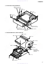
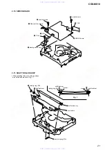
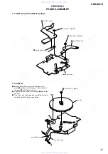
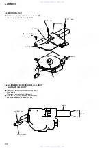
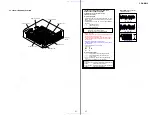
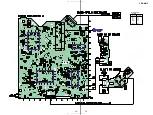
3-3. MOTOR BLOCK
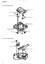
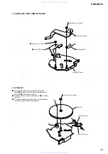
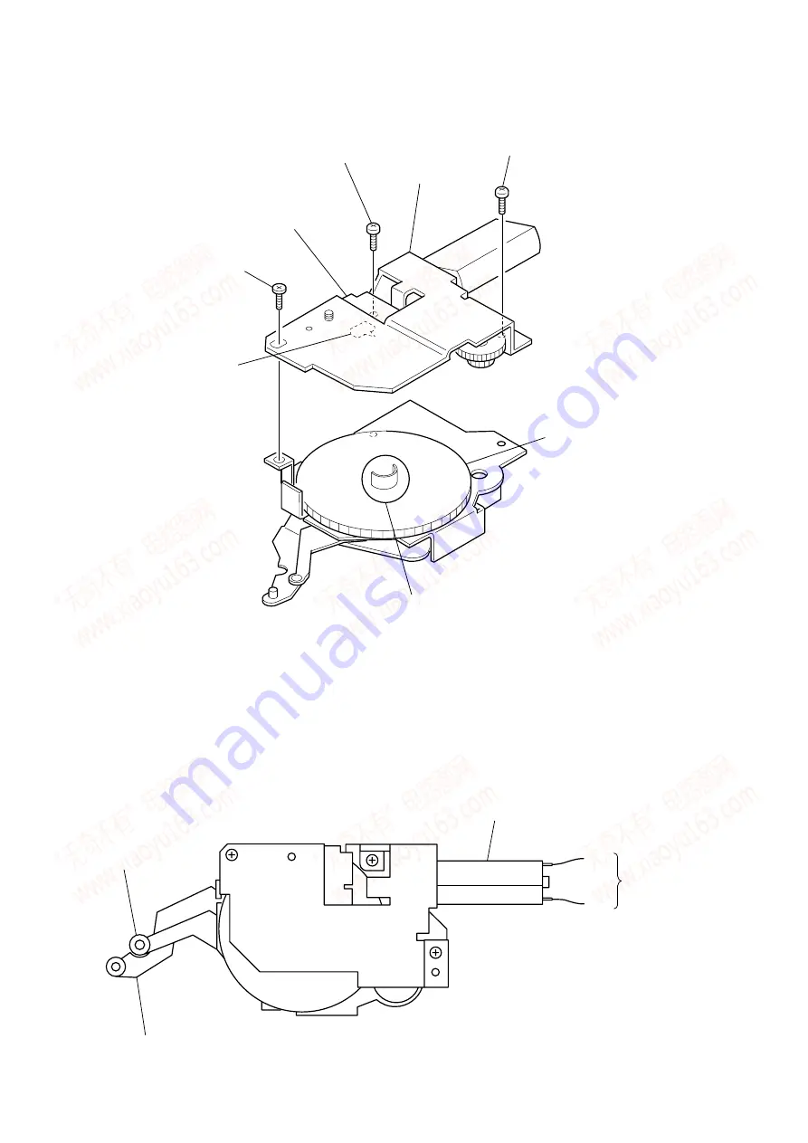
3-4. ALIGNMENT BETWEEN ARM (A-L) ASSY
AND ARM (B-L) ASSY
1
Turn the cam (L) and position the cam so that part
A
does not touch the SWITCH board SW900.
1
Input 9V DC to the motor terminal until the cam (L)
stops rotating.
Take care to avoid overload of the motor.
Verify that the arm (A-L) assy and arm (B-L) assy
are positioned as shown below (full open).
3
PTT 2.6x6
4
PTT 2.6x6
2
motor block
SWITCH board
SW900
cam (L)
5
screw (+BTT)
A
motor
GND
arm (A-L) assy
DC 9V
+B
www. xiaoyu163. com
QQ 376315150
9
9
2
8
9
4
2
9
8
TEL 13942296513
9
9
2
8
9
4
2
9
8
0
5
1
5
1
3
6
7
3
Q
Q
TEL 13942296513 QQ 376315150 892498299
TEL 13942296513 QQ 376315150 892498299


