– 21 –
TP
SHUF
TP
SHUF
TP
SHUF
AM RF signal
generator
antenna
terminal
AM dummy
antenna(50
Ω
)
30
Ω
65 pF
15 pF
set
SHUF
SHUF
FM RF signal
generator
antenna
terminal
0.01
µ
F
set
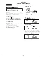
MW Auto Scan/Stop Level Adjustment
Setting :
SOURCE
n
MODE button : MW
Procedure :
1. Set to the test mode. (See page 19.)
2. Push the SOURCE button.
3. Push the MODE button and set to MW.
Display
4. Push the preset 3 button.
Display
5. Adjust with the volume RV1 on TU10 so that the “MW”
indication turns to “MW0” indication on the display window.
But, in case of already indicated “MW0”, turn the RV1 so that
put out light “0” indication and adjustment.
Display
Carrier frequency : 999 kHz
30% amplitude
modulation by
1 kHz signal
output level
: 33 dB (44.7
µ
V)
Adjustment Location : See page 22.
Carrier frequency : 98.00 MHz
Output level
: 35 dB (56.2
µ
V)
Mode
: mono
Modulation
: no modulation
Procedure :
1. Set to the test mode. (See page 19.)
2. Push the SOURCE button and set to FM.
Display
FM RDS S-Meter Adjustment
Setting :
SOURCE button : FM
3. Push the preset 10 button.
4. Adjust RV10 so that the display indication is “13.0”.
Display
Specification : Display indication : 12.8 to 13.2.
Adjustment Location : See page 22.
Summary of Contents for CDX-C7850R
Page 3: ... 3 SECTION 1 GENERAL This section is extracted from instruction manual ...
Page 4: ... 4 ...
Page 5: ... 5 ...
Page 6: ... 6 ...
Page 7: ... 7 ...
Page 8: ... 8 ...
Page 9: ... 9 ...
Page 10: ... 10 ...
Page 11: ... 11 ...
Page 12: ... 12 ...
Page 39: ... 47 48 CDX C7850R Page 51 ...
Page 41: ...CDX C7850R 51 52 Page 65 Page 66 Page 47 ...
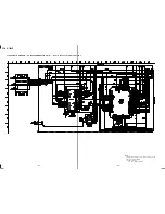
Page 49: ... 67 4 18 SCHEMATIC DIAGRAM RELAY SECTION Page 63 Page 60 Page 60 CDX C7850R ...

