– 20 –
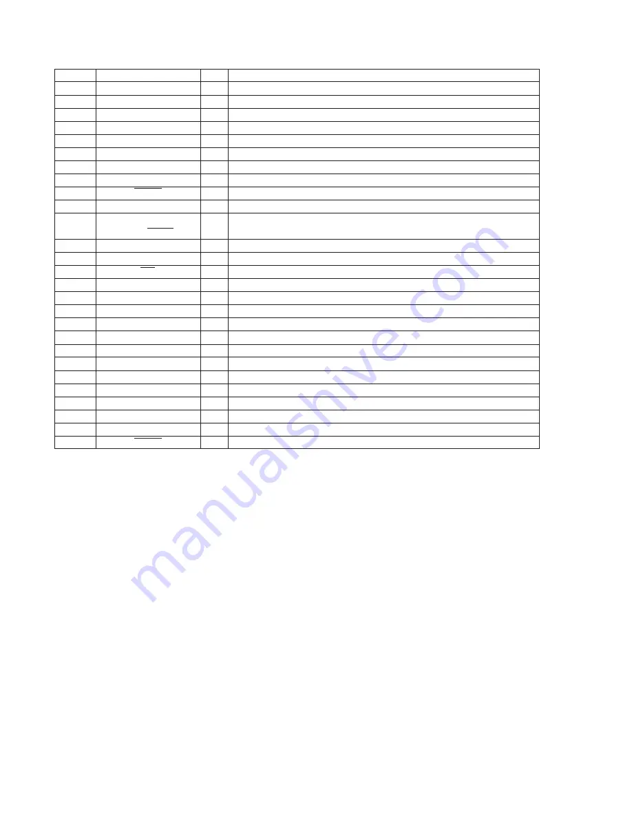
Pin No.
Pin Name
I/O
Pin Description
54
ILL-ON
O
Illumination output
55
C.ALARM
I
Caution alarm select input (Used/Not used)
56
NC
I
Not used (Connect to ground)
57
NC
—
Fixed at “H” in this set.
58
LCD-CE
O
LCD drive chip select output
59
EZ-SEL
I
SHIFT + input
60
SENS
I
Information input from servo IC.
61
FOK
I
Focus OK input
62
LD-ON
O
Laser diode control
63
NC
—
Not used. (Connect to ground)
64
[IN] ST/MONO
I/O
Used for both STEREO indicator display input and force MONO output. (FM)
[OUT] MONO
65
LCD-CKO
O
LCD driver serial clock output
66
LCD-So
O
LCD driver serial data output
67
INH
O
INHbit output
68
SQ-CKo
O
Q data read serial clock output
69
CD-RST
O
Servo IC/DAC reset output
70
SQ-SI
I
Q data input
71
CD-SO
O
Serial data output to servo IC.
72
CD-LAT
O
Data latch output to servo IC.
73
CD-CKO
O
Serial clock output to servo IC.
74
VREF
—
Not used.
75
GND1
—
Ground
76
X-OUT
—
Crystal oscillator connection (4.5 MHz)
77
X-IN
I
Crystal oscillator connection (4.5 MHz)
78
BU-IN
I
Back-up detection
79
VDD1
—
Power supply (+5 V)
80
RESET
I
RESET input


