background image

— 37 —

SECTION  6

EXPLODED VIEWS

NOTE:

• Items marked “*” are not stocked since they are

seldom required for routine service. Some delay
should be anticipated when ordering these items.

• The mechanical parts with no reference number in

the exploded views are not supplied.

• Hardware (# mark) list and accessories and pack-

ing materials are given in the last of this parts list.

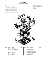
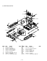
6-1. TOP PLATE ASSEMBLY SECTION

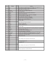
The components identified by
mark 

!

 or dotted line with mark

!

 are critical for safety.

Replace only with part number
specified.

Ref. No.

Part No.

Description

Remark

Ref. No.

Part No.

Description

Remark

1

4-960-910-21 SCREW, ORNAMENTAL

2

4-979-021-01 PLATE (A), TOP

3

4-979-026-01 PLATE (B), ORNAMENTAL

4

4-960-910-11 SCREW, ORNAMENTAL

5

4-979-028-01 WINDOW, DISC

6

4-979-039-01 HOLDER (R)

7

4-979-027-01 PLATE (F), ORNAMENTAL

*

8

4-927-881-01 SHEET, ADHESIVE

9

4-924-233-01 INDICATOR

10

4-979-030-01 SLIDER

11

4-979-045-01 SLIDER (B)

12

4-979-020-01 PLATE (B), TOP

13

4-979-025-01 PLATE (D), ORNAMENTAL

14

4-979-031-01 BUTTON, CONTROL

*

15

A-4673-795-A KEY BOARD, COMPLETE

16

4-979-043-01 PULLEY, DISK

17

4-980-533-01 DAMPER (B)

5

13

7

not supplied

4

16

1

2

3

1

2

6

10

9

8

14

12

15

11

17

not supplied

not supplied

#1

#1

#1

#1

#2

#2

A

B

C

B

A

C

not
supplied

10

#15

#15

#15

#15

Summary of Contents for CDP-X5000

Page 1: ...l Name Using Similar Mechanism NEW Base Unit Type BU 12A Optical Pick up Type KSS 274A J N SPECIFICATIONS MICROFILM COMPACT DISC PLAYER CDP X5000 AEP Model UK Model E Model Chinese Model SERVICE MANUAL General ...

Page 2: ...31 6 EXPLODED VIEWS 6 1 Top Plate Assembly Seciton 37 6 2 Front Panel Section 38 6 3 Back Panel Section 39 6 4 Base Unit Section BU 12A 40 7 ELECTRICAL PARTS LIST 41 The laser component in this product is capable of emitting radiation exceeding the limit for Class 1 Notes on chip component replacement Never reuse a disconnected chip component Notice that the minus side of a tantalum capacitor may ...

Page 3: ...f the standard disc YEDS 18 is written in the non volatile memory IC203 X24C01S of the servo board so that the gain need not be re adjusted when changing discs Therefore if the servo board IC203 of the servo board or optical pick up has been replaced be sure to write the auto gain data 1 Connect TP ADJ Pin 3 of CN515 to GND Ground and turn ON the POWER switch 2 Insert the test disc YEDS 18 The TOC...

Page 4: ...tton PROGRAM button C INDEX button 3 Number buttons 1 20 4 CLEAR button 5 20 button 6 CHECK button 7 REPEAT button 8 A B button 9 play button º AMS buttons C c index search buttons TIME button MUSIC SCAN button SPACE button FADER button PEAK SEARCH button ERASE button FILE button ª p stop button º P pause button 0 fast forward fast rewind buttons 0 SLOW buttons 1 POWER switch 2 Disc lid 3 0 fast f...

Page 5: ... 5 ...

Page 6: ... 6 ...

Page 7: ... 7 ...

Page 8: ...procedure in the numerical order given 3 1 TOP PLATE ASSEMBLY 1 Connectors CN207 CN208 SERVO board 2 Two bolts M3 3 Two bolts M3 4 Front panel assembly 1 Four ornamental screws 2 Top plate assembly 3 Connector CN805 Display board 3 2 FRONT PANEL ASSEMBLY ...

Page 9: ...crew B 3X8 3 Ground wire 4 Four screws B 2 6X6 5 Boss M Four pieces 6 Base unit Spring 3 4 BACK PANEL 1 Connectors CN305 A OUT board CN502 CN508 CN509 CN512 AUDIO board 2 Screw B 3X8 3 Ground wire 4 Two screws B 3X6 6 Back panel assembly 5 Three screws BV 3X8 ...

Page 10: ...Turn Power switch on 3 Put disc YEDS 18 in and playback 4 Confirm that oscilloscope waveform is clear and check RF signal level is correct or not Note A clear RF signal waveform means that the shape can be clearly distinguished at the center of the waveform RF signal waveform E F Balance Check Procedure 1 Connect test point TP ADJ CN515 3pin to Ground and TP TEI IC101 pin to TP VC CN210 pin with a...

Page 11: ... to TP RF 1Pin of CN215 7 While pressing the and buttons press the POWER but ton The discrete open close detection is turned OFF 8 Set a disk YEDS 18 and press the button 9 Rotate the adjustment screw with a Phillips screwdriver and ad just so that the oscilloscope waveform becomes clear Note A clear RF signal waveform means that the shape can be clearly distinguished at the center of the waveform...

Page 12: ... 5 DIAGRAMS 5 1 CIRCUIT BOARDS LOCATION AC IN board B OUT board BSL board AC SW board DISPLAY board AUDIO board KEY board S POWER board OUT SW board OPTICAL board FLEXIBLE board SERVO board A OUT board U OUT board ...

Page 13: ...g EFM PLL Open VCO output for analog EFM PLL Connected to Ground TEST pin connected normally to Ground Connected to Ground Digital Ground TEST pin connected normally to Ground TEST pin connected normally to Ground Charge pump output for analog EFM PLL Open Charge pump output for variable pitch PLL Open Clock input from variable pitch external VCO Connected to Ground Analog power supply Power suppl...

Page 14: ...DA 11 output when PSSL 1 GTOP output when PSSL 0 Open DA 10 output when PSSL 1 XUGF output when PSSL 0 Open DA 09 output when PSSL 1 XPLCK output when PSSL 0 DA 08 output when PSSL 1 GFS output when PSSL 0 DA 07 output when PSSL 1 RFCK output when PSSL 0 DA 06 output when PSSL 1 C2PO output when PSSL 0 Open DA 05 output when PSSL 1 XRA0F output when PSSL 0 Open DA 04 output when PSSL 1 MNT3 output...

Page 15: ...d Input pin for anti shock Connected to Ground Serial data input supplied from CPU Latch input supplied from CPU Serial data transfer clock input supplied from CPU Numbers of track counted signal output Open Digital power supply Mirror signal output Open Defect signal output Open Focus OK output Open Output to select spindle motor output filter Open Output to control ON OFF of spindle motor Open O...

Page 16: ...otor volume up output Not used Headphone motor volume down output Not used Blank output to fluorescent indicator tube driver LC7570E When the indicator tube lights H Serial data output to fluorescent indicator tube driver LC7570E Clock output to fluorescent indicator tube driver LC7570E Latch output to fluorescent indicator tube driver LC7570E Senser powr supply ON OFF control output for stabilize...

Page 17: ...h to digital filter Serial data transfer clock output to CXD2515AQ CXD8504M SENSE signal input from CXD2515AQ Serial data output to CXD2515AQ CXD8504M Sub code Q read out clock output to CXD2515AQ Sub code Q data input from CXD2515AQ Not used Open Model distinction Connected to Ground Remote contrl signal input Not used Connected to 5V Not used Open Sub code sync input from CXD2515AQ Start to read...

Page 18: ...because of the positional relation between the BSL coil and Hall element The BSL IC104 IC105 driver is therefore muted while the lid is open BLANK This port is required because the display tube in this set static lights up and a dedicated screwdriver is required It is basically a RESET pin But as problems will occur if used also as RESET timings are specially provided using the micro processor ...

Page 19: ......

Page 20: ......

Page 21: ......

Page 22: ......

Page 23: ...cified Ref No Part No Description Remark Ref No Part No Description Remark 1 4 960 910 21 SCREW ORNAMENTAL 2 4 979 021 01 PLATE A TOP 3 4 979 026 01 PLATE B ORNAMENTAL 4 4 960 910 11 SCREW ORNAMENTAL 5 4 979 028 01 WINDOW DISC 6 4 979 039 01 HOLDER R 7 4 979 027 01 PLATE F ORNAMENTAL 8 4 927 881 01 SHEET ADHESIVE 9 4 924 233 01 INDICATOR 10 4 979 030 01 SLIDER 11 4 979 045 01 SLIDER B 12 4 979 020...

Page 24: ...9 510 01 HOLDER FL FL801 1 517 357 11 INDICATOR TUBE FLUORESCENT 51 3 910 074 31 BOLT M3 52 4 979 033 01 PANEL FRONT 53 4 979 042 01 WINDOW INDICATION 54 X 4946 608 1 BUTTON ASSY POWER 55 4 960 910 21 SCREW ORNAMENTAL 56 4 979 034 01 PANEL SIDE 57 A 4673 794 A DISPLAY BOARD COMPLETE 58 1 659 241 11 AC SW BOARD 59 A 4673 792 A S POWER BOARD COMPLETE not supplied 51 57 not supplied not supplied 59 5...

Page 25: ... 247 11 A OUT BOARD 113 4 983 748 01 PANEL BACK 114 3 704 515 41 SCREW BV RING 115 2 259 121 01 SCREW TR 116 3 704 515 21 SCREW BV RING 118 4 967 960 01 SCREW 4X8 IC951 8 759 604 86 IC M5F7807L IC953 8 759 604 90 IC M5F7907L T1 1 429 750 11 TRANSFORMER POWER 1 1 not supplied 110 109 111 113 104 114 108 not supplied 103 105 not supplied 115 115 115 115 101 IC951 IC953 14 not supplied 103 14 12 14 1...

Page 26: ...4 968 916 01 BRACKET OP BASE 814 4 968 865 01 GEAR C 815 4 968 879 01 SPRING OP LEAF 816 4 917 562 11 INSULATOR 817 4 968 862 01 BASE MECHANICAL 818 4 968 864 01 GEAR B 819 1 653 918 11 FLEXIBLE BOARD 820 4 979 955 01 PULLEY S1 DISC 821 4 970 924 01 SPRING SKEW LEAF 822 3 701 444 11 WASHER 6 823 4 943 342 01 BEARING M21 X 4945 920 1 MOTOR ASSY SLED S21 1 571 958 11 SWITCH PUSH 1 KEY LIMIT OUT S22 ...

Page 27: ...0PF 5 100V C417 1 136 817 91 FILM 0 0033uF 5 100V C418 1 136 813 11 FILM 680PF 5 100V C419 1 115 196 11 FILM 0 47uF 5 200V C423 1 136 850 11 FILM 0 1uF 5 63V C428 1 136 850 11 FILM 0 1uF 5 63V C429 1 136 850 11 FILM 0 1uF 5 63V C430 1 128 200 11 ELECT 47uF 20 63V C431 1 130 973 00 FILM 0 022uF 3 100V C432 1 130 969 11 FILM 0 012uF 3 100V C433 1 130 969 11 FILM 0 012uF 3 100V C434 1 130 856 00 FILM...

Page 28: ...9 296 74 IC AD712JR REEL IC502 8 759 296 74 IC AD712JR REEL IC503 8 759 296 74 IC AD712JR REEL IC504 8 759 371 51 IC CXA8042AS IC551 8 759 242 70 IC TC7WU04F IC601 8 759 334 74 IC CXD8504AM IC603 8 759 044 10 IC CXD2562Q IC605 8 759 231 53 IC TA7805S IC608 8 759 604 90 IC M5F7907L IC921 8 759 296 74 IC AD712JR REEL IC922 8 759 296 74 IC AD712JR REEL IC951 8 759 604 86 IC M5F7807L IC952 8 759 231 5...

Page 29: ...BON MELF 330 2 1 8W R583 1 259 989 11 CARBON MELF 330 2 1 8W R584 1 259 989 11 CARBON MELF 330 2 1 8W R601 1 259 995 11 CARBON MELF 1K 2 1 8W R602 1 259 995 11 CARBON MELF 1K 2 1 8W R603 1 259 995 11 CARBON MELF 1K 2 1 8W R607 1 249 415 11 CARBON 680 5 1 4W F R608 1 259 991 11 CARBON MELF 470 2 1 8W R609 1 259 991 11 CARBON MELF 470 2 1 8W R610 1 259 991 11 CARBON MELF 470 2 1 8W R611 1 259 991 11...

Page 30: ... 1 KEY LIMIT OUT S22 1 571 958 11 SWITCH PUSH 1 KEY LIMIT IN A 4673 795 A KEY BOARD COMPLETE CAPACITOR C954 1 163 125 00 CERAMIC CHIP 220PF 5 50V DIODE D871 8 719 303 02 DIODE SEL2510C D D872 8 719 301 53 DIODE SEL2810A D P TRANSISTOR Q871 8 729 900 53 TRANSISTOR DTC114EK Q872 8 729 900 53 TRANSISTOR DTC114EK RESISTOR R850 1 249 415 11 CARBON 680 5 1 4W F R851 1 259 995 11 CARBON MELF 1K 2 1 8W R8...

Page 31: ... 5 50V C107 1 163 809 11 CERAMIC CHIP 0 047uF 10 25V C108 1 163 145 00 CERAMIC CHIP 0 0015uF 5 50V C109 1 163 117 00 CERAMIC CHIP 100PF 5 50V C110 1 164 489 11 CERAMIC CHIP 0 22uF 10 16V C111 1 164 232 11 CERAMIC CHIP 0 01uF 50V C112 1 164 004 11 CERAMIC CHIP 0 1uF 10 25V C113 1 164 004 11 CERAMIC CHIP 0 1uF 10 25V C114 1 164 004 11 CERAMIC CHIP 0 1uF 10 25V C115 1 136 177 00 FILM 1uF 5 50V C116 1...

Page 32: ...70 2 1 10W R114 1 208 425 41 METAL GLAZE 330 2 1 10W R115 1 208 462 41 METAL GLAZE 10K 2 1 10W R116 1 208 437 41 METAL GLAZE 1K 2 1 10W R117 1 208 462 41 METAL GLAZE 10K 2 1 10W R118 1 216 699 11 METAL CHIP 100K 0 5 1 10W R119 1 216 687 11 METAL CHIP 33K 0 5 1 10W R120 1 208 345 11 METAL GLAZE 15 2 1 10W R121 1 208 345 11 METAL GLAZE 15 2 1 10W R131 1 216 689 11 METAL CHIP 39K 0 5 1 10W R132 1 216...

Page 33: ...11 WIRE FLAT TYPE 64 1 776 182 11 WIRE FLAT TYPE 805 8 848 466 11 OPTICAL PICK UP BLOCK KSS 274A J N 819 1 653 918 11 FLEXIBLE BOARD FL801 1 517 357 11 INDICATOR TUBE FLUORESCENT IC951 8 759 604 86 IC M5F7807L IC953 8 759 604 90 IC M5F7907L M21 X 4945 920 1 MOTOR ASSY SLED S21 1 571 958 11 SWITCH PUSH 1 KEY LIMIT OUT S22 1 571 958 11 SWITCH PUSH 1 KEY LIMIT IN T1 1 429 750 11 TRANSFORMER POWER ACC...

Page 34: ... 48 CDP X5000 9 960 429 11 Sony Corporation Home A V Products Company English 96F0961 1 Printed in Japan 1996 6 Published by Quality Engineering Dept Shibaura ...

Reviews: