8
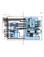
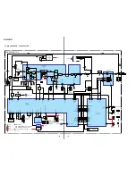
D-F200/F201
US,CND,E92,
AR,MX MODEL
30
31
60
61
90
91
120
1
TP33
TP630
TP601
TP602
TP605
TP604
TP603
TP606
TP626
TP627
R604
C627
R602
C606
C607
C613
C624
R622
R601
VDR601
C602
C630
C611
R630
R452
R451
C310
R612
R629
C612
R616
R614
R606
C614
R609
R607
R605
R623
R652
C626
R611
R651
C605
FB601
R613
C604
L603
R617
C621
L604
C610
C608
C617
IC601
R620
C618
R618
R653
R654
C609
R619
R615
C601
X601
R625
D602
C641
D603
R647
TP412
TP410
C616
TP603
RF
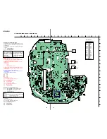
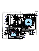
– MAIN BOARD (SIDE B) –
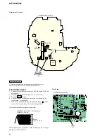
Adjustment Location:
CD SECTION
CD section adjustments are done automatically in this set.
In case of operation check, confirm that focus bias.
FOCUS BIAS CHECK
1. Connect the oscilloscope between TP603 (RF) and GND on
main board.
2. Insert the disc (YEDS-18). (Part No. : 3-702-101-01)
3. Press the
N
X
button.
4. Confirm that the oscilloscope waveform is as shown in the
figure below. (eye pattern)
A good eye pattern means that the diamond shape ( ) in the
center of the waveform can be clearly distinguished.
• RF signal reference waveform (eye pattern)
Test Point:
When observing the eye pattern, set the oscilloscope for AC range
and raise vertical sensitivity.
CN501
IC51
TP81
VT
TP3
RF-IN
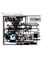
– MAIN BOARD (SIDE A) –
CT3 L4
L3
L1
CT1
L2
FM TRACKING ADJ
AM IF ADJ
T1
AM TRACKING
ADJ
RF level :
0.45
±
0.1 Vp-p
VOLT/DIV : 20 mV (10 : 1 probe in use)
TIME/DIV : 500 nS

