– 22 –
AT2X
RM-EA001/RM-ED001
1.
Remove the rear cover (See 2-1).
2.
Remove the main brackets (See 2-3).
3.
Disconnect the harnesses connected to boards beneath the main shield case (NP1, BL and N boards). Remove the main shield case.
4.
Remove the NP1, BL and N boards (See 2-7).
5.
Remove the A2 board (See 2-6).
6.
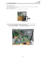
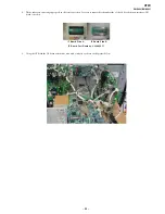
Place a support of approx 35cm high as close as possible to the TV set as shown below.
7.
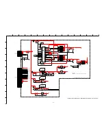
Arrange the removed circuit boards as shown in the picture. Reconnect the interconnecting harnesses to the circuit boards.
Note: Two new cables are needed to connect the boards in the service position
Cable 1: Part Number: 9-948-020-73
G3L board CN6200, CN6201 to NP1 board CN5801, CN5802
Cable 2: Part Number: 9-948-020-72
N board CN3402 to A2 board CN5105
2-12.SERVICE POSITION
35cm
Summary of Contents for Bravia KLV-V40A10E
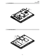
Page 16: ... 16 AT2X RM EA001 RM ED001 SECTION 2 DISASSEMBLY 2 2 STAND REMOVAL 2 1 REAR COVER REMOVAL ...
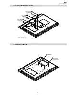
Page 17: ... 17 AT2X RM EA001 RM ED001 2 3 BRACKET REMOVAL 2 4 LOUDSPEAKER REMOVAL ...
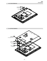
Page 18: ... 18 AT2X RM EA001 RM ED001 2 5 FAN REMOVAL 2 6 A2 BOARD REMOVAL ...
Page 19: ... 19 AT2X RM EA001 RM ED001 2 7 BL N and NP1 BOARD REMOVAL 2 8 G3L BOARD REMOVAL ...
Page 20: ... 20 AT2X RM EA001 RM ED001 2 9 H7 BOARD REMOVAL 2 10 H8 BOARD REMOVAL ...
Page 21: ... 21 AT2X RM EA001 RM ED001 2 11 H6 BOARD REMOVAL ...


