


KDS-50A3000/55A3000/60A3000
KDS-50A3000/55A3000/60A3000
14
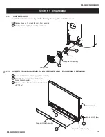
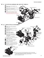
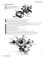
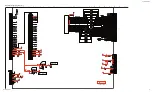
1-7. CHASSIS
REMOVAL
2
1
FB1A Block Assembly
AC Bracket
(F Board Bracket)
Chassis Block
1 Remove 2 screws from the Rear Cabinet and the
AC Bracket, +BVTP 3x12 TYPE2 IT-3
2 Remove 2 screws from the FB1A Block Assembly,
+BVTP2 4x16
7
8
9
13
14
6
4
3
5
10
11
12
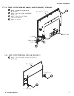
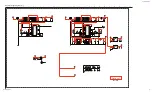
Fan Bracket
G Board
A Board
D.C. Fan (60x60)
Turn Rivet
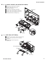
Terminal Bracket
U Board
G Bracket
AU Shield
BC Board
BC Shield
FB1 Block
TUU2 Block
F Board
3 G Board – Disconnect 6 connectors then remove 6 screws, +BVTP 3x12 TYPE2 IT-3
4 Fan Bracket – Disconnect 1 Connector then remove 2 screws, +BVTP2 4x16
5 Turn Rivet – Unscrew and carefully pull out from the fan to release it from the shield.
Note: The fan is secured to the Chassis Assembly with Turn Rivet screws. To remove these screws use a screw driver to unscrew the
screw until it lifts slightly above the rivet then pull the screw and the rivet out from the fan.
6 A Board – Disconnect 2 connectors then remove 3 screws, +BVST3x6, and pull out from the FB1A Block Assembly connector
7 F Board – Disconnect 2 connectors then remove 2 screws, +BVST 3x6
8 TUU2 Block – Release the RF connector
9 FB1A Block Assembly – Disconnect 6 connectors
10 BC Board – Disconnect 2 connectors then remove 2 screws, +BVST 3x6
11 BC Shield – Remove 3 screws, +BVST 3x6
12 G Bracket – Remove 6 screws, +BVST 3x6, then remove the AU Shield by removing 1 screw, +BVST 3x6
13 U Board – Disconnect 1 connector, remove 2 BVST 3x6, and pull out from FB1A Block Assembly connector
14 Terminal Bracket - Remove 3 screws, +PSW M3x8, 5 screws, + BVTP 3x12 TYPE2 IT-3, and 1 Hex Nut and 1 Washer
Caution: When replacing any part of the chassis be sure to remove any dust particles and clean the mirror.


