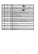

– 19 –
Pin No.
Pin name
I/O
Description
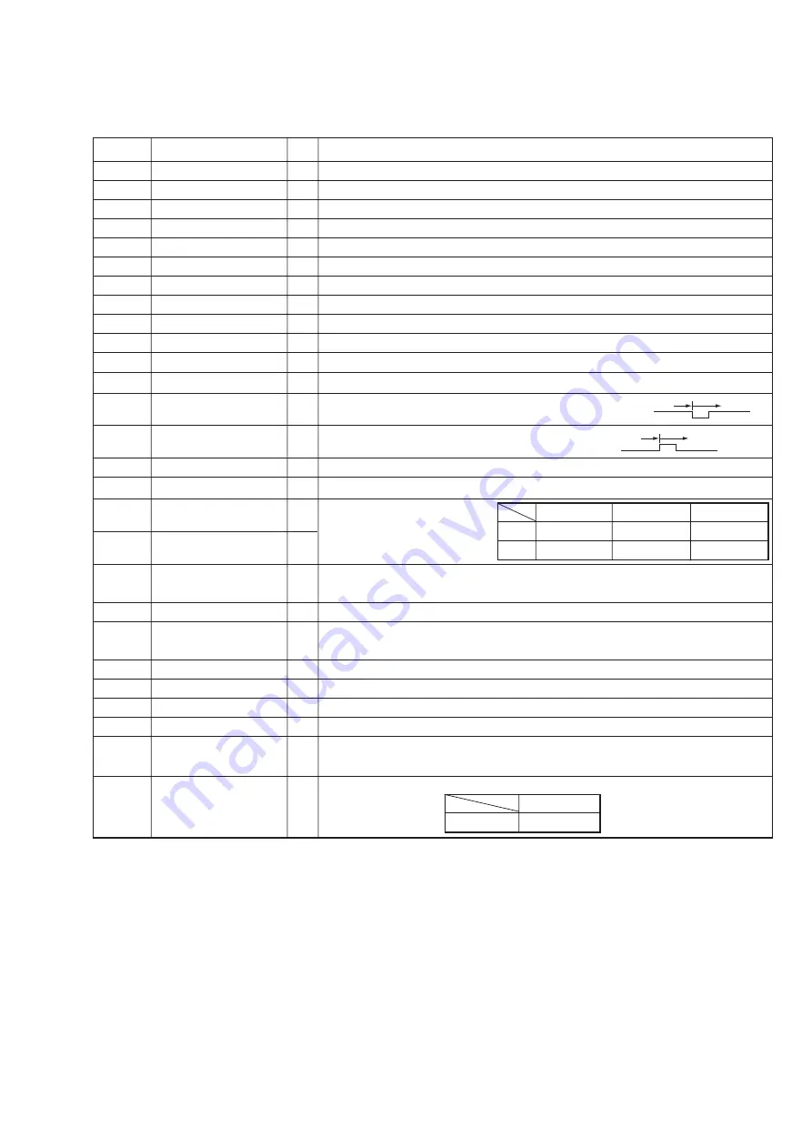
1 – 12
S12 – S23
–
Not used (OPEN).
13 – 16
KOUT 0 – KOUT 3
O
Key scan output.
17
MA50 - OUT
–
Not used (OPEN).
18
–
–
Not used (OPEN).
19
4.8 / 2.4 - OUT
O
Tape speed change signal output.
20
–
–
Not used (OPEN).
21– 23
COM0 – COM2
–
Not used (OPEN).
24
–
–
Not used (OPEN).
25
LCD - BIAS
–
Conect to VSS.
26 – 28
VLCD0 – VLCD2
–
Conect to VSS.
––––––––––––––––
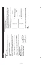
29
FE-OUT
O
Fast-Erase control output. At Fast-Erase : “ L ” At the other : “ H ”
–––––––––––––––––––––
30
BIAS-OUT
O
BIAS control output. At DICT, TEL-REC : 0V At the other : 5.9V
–––––––––––––––––––––––––––
31
BRK-PG-OUT
O
Brake plunger output. Normal : 6.0 V STOP from FF/REW :
FF/REW
STOP
60ms
0V
–––––––––––––––––––––––––––
32
STOP-PG-OUT
O
Stop plunger output. Normal : 0 V STOP from FWD :
FWD
STOP
60ms
0V
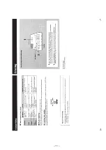
33
VSS
–
GND
–––––––––––––––––
34
FWD-PG-OUT
O
FWD plunger output. At FWD : “ H ” At the other : “ L ”
––––––––––
35
FF-M-OUT
O
FF/REW motor output.
–––––––––––––––
36
REW-M-OUT
O
37
A-OFF-OUT
O
Motor Auto-off output.
Motor Auto-off (no cassette or after three minutes after STOP) : “ H ” At the other : “ L ”
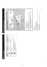
38
STAND-BY
I
POWER switch input. POWER switch ON : “ H ” POWER switch OFF : “ L ”
39
TAB-IN
I
TAB (erase proof) detection switch input.
Cassette with TAB : “ L ” Cassette without TAB : “ H ”
40
MC-IN
I
Cassette detection switch input. With a cassette : “ L ” Without a cassette : “ H ”
41
CAS-IN
I
Cassette detection switch input. With a cassette : “ L ” Without a cassette : “ H ”
42
SR
I
S reel signal input.
43
TR
I
S reel signal input.
––––––––––
44
DICT-IN
I
HU-DICT key input.
At DICT key input of the hand control unit (HU-80) : “ L ” At the other : “ H ”
45
LTR-DET
I
LTR signal input. Count the rectangular pulse with microcomputer
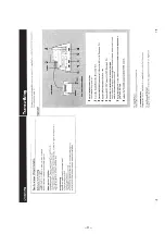
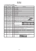
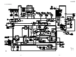
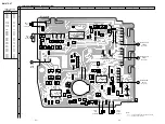
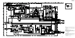
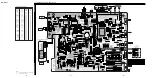
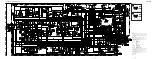
SECTION 6
DIAGRAMS
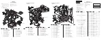
6-1. EXPLANATION OF IC TERMINALS
IC109
µ
PD75308GF-J16-3B9 (SYSTEM CONTROL)
At motor FF
At motor REW
At the other
Pin35
L
H
H
Pin36
H
L
H
LTR
At FF/REW
600 to 4,800HZ
Summary of Contents for BM-87DST Marketing
Page 3: ... 3 SECTION 2 GENERAL This section is extracted from instruction manual ...
Page 4: ... 4 ...
Page 5: ... 5 ...
Page 6: ... 6 ...
Page 7: ... 7 ...
Page 8: ... 8 ...
Page 9: ... 9 ...
Page 10: ... 10 ...
Page 11: ... 11 ...
Page 12: ... 12 ...
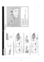
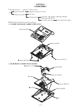
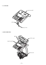
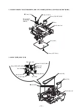
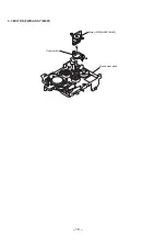
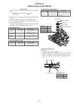
Page 16: ... 16 3 7 MOTOR FWD ASSY M901 3 1 2 Motor FWD ASSY M901 Mechanism deck Cushion M ...
Page 21: ... 21 22 BM 87DST 6 2 BLOCK DIAGRAM Note Signal path E PB a REC ...
Page 31: ... 43 BM 87DST MEMO ...


