XBR/KD-84X9000 Series(WW)
4
WARNINGS AND CAUTIONS
- ENGLISH
CAUTION
These servicing instructions are for use by qualified service personnel only.
To reduce the risk of electric shock, do not perform any servicing other than that contained in the operating instructions unless you are qualified to do so.
WARNING!!
An isolation transformer should be used during any service to avoid possible shock hazard, because of live chassis.
The chassis of this receiver is directly connected to the ac power line.
CARRYING THE TV
Be sure to follow these guidelines to protect your property and avoid causing serious injury.
• Carry the TV with an adequate number of people; larger size TVs require two or more people.
• Correct hand placement while carrying the TV is very important for safety and to avoid damages.
SAFETY-RELATED COMPONENT WARNING!!
Components identified by shading and ! mark on the schematic diagrams, exploded views, and in the parts list are critical for safe operation. Replace these components with Sony
parts whose part numbers appear as shown in this manual or in supplements published by Sony. Circuit adjustments that are critical for safe operation are identified in this manual.
Follow these procedures whenever critical components are replaced or improper operation is suspected.
Summary of Contents for AZ3SR
Page 2: ...SERVICE MANUAL LCD Digital Color TV AZ3SR CHASSIS Segment FS H 9 888 517 05 ...
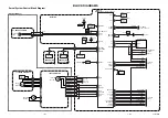
Page 98: ...XBR KD 84X9000 Series WW 98 SEC 4 DIAGRAMS 4 1 BLOCK DIAGRAM 4 1 1 KD 84X9000 CH ...
Page 99: ...XBR KD 84X9000 Series WW 99 DIAGRAMS 4 1 2 XBR 84X900 U C ...
Page 100: ...XBR KD 84X9000 Series WW 100 DIAGRAMS 4 1 3 KD 84X9005 AEP ...
Page 101: ...XBR KD 84X9000 Series WW 101 DIAGRAMS 4 1 4 KD 84X9000 AF AUS HK TW AND XBR 84X905 LA6 ...
Page 102: ...XBR KD 84X9000 Series WW 102 DIAGRAMS 4 2 CONNECTOR DIAGRAM 1 4 ...
Page 103: ...XBR KD 84X9000 Series WW 103 DIAGRAMS 4 2 CONNECTOR DIAGRAM 2 4 ...
Page 104: ...XBR KD 84X9000 Series WW 104 DIAGRAMS 4 2 CONNECTOR DIAGRAM 3 4 ...
Page 105: ...XBR KD 84X9000 Series WW 105 DIAGRAMS 4 2 CONNECTOR DIAGRAM 4 4 ...
Page 128: ...XBR KD 84X9000 Series WW 128 REMOTE COMMANDER PACKING INSTRUCTION REMOTE COMMANDER APPENDIX 2 ...
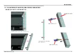
Page 137: ...XBR KD 84X9000 Series WW 137 SUPPORTING INFORMATION FOR ASSEMBLEY PROTECT TAB C APPENDIX 3 ...
Page 139: ...XBR KD 84X9000 Series WW 139 SUPPORTING INFORMATION FOR ASSEMBLEY LABEL PANEL APPENDIX 3 ...
Page 142: ...XBR KD 84X9000 Series WW 142 SUPPORTING INFORMATION FOR ASSEMBLEY BRACKET PANEL APPENDIX 3 ...
Page 143: ...XBR KD 84X9000 Series WW 143 SUPPORTING INFORMATION FOR ASSEMBLEY BRACKET PANEL APPENDIX 3 ...
Page 144: ...XBR KD 84X9000 Series WW 144 SUPPORTING INFORMATION FOR ASSEMBLEY BRACKET PANEL APPENDIX 3 ...
Page 145: ...XBR KD 84X9000 Series WW 145 SUPPORTING INFORMATION FOR ASSEMBLEY BRACKET PANEL APPENDIX 3 ...
Page 150: ...XBR KD 84X9000 Series WW 150 SUPPORTING INFORMATION FOR ASSEMBLEY SHEET AL CV APPENDIX 3 ...


