


HCD-EC59/EC590
7
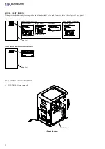
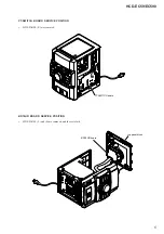
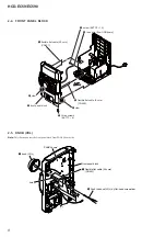
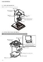
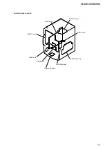
2-3. TOP PANEL ASSY
5
two claws
3
connector
(SW305)
2
two screws
(BVTP3
u
10)
1
screw
(KTP3
u
10)
1
screw
(KTP3
u
10)
6
Lift up the side of the top panel assy in the back and
remove the two claws in front of the top panel assy.
7
top panel assy
4
flexible flat cable (25 core)
(CN403)
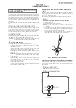
Note:
Follow the disassembly procedure in the numerical order given.
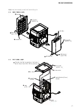
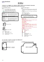
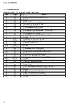
2-2. SIDE PANEL (L)/(R)
2
two screws
(BVTP3
u
10)
5
side panel (L)
5
side panel (R)
1
three screws
(case 3 TP2)
4
two claws
3
3
2
two screws
(BVTP3
u
10)
1
three screws
(case 3 TP2)
4
two claws