background image

- 9 -

10

Introducing a

n

d Usi

ng the Me

nu System

Yo

ur

 T

V u

ses 

an

 O

n-

S

cr

een

 m

enu

 syst

em

 t

o

 g

u

id

you

 t

h

rou

gh

 t

h

ope

ra

ti

ons

Use

 t

h

e f

o

ll

o

wi

ng

 but

to

ns 

on


th

Remo

te 

C

o

n

tro

to 

o

p

erate

 th

menu

 s

ystem

1

To 

switch

 o

n

 th

men

u

 sc

reen

s:

P

res

th

ME

N

U

 bu

tto

to 

sw

it

ch

 t

he

 first 

le

ve

l m

enu

 o

n.

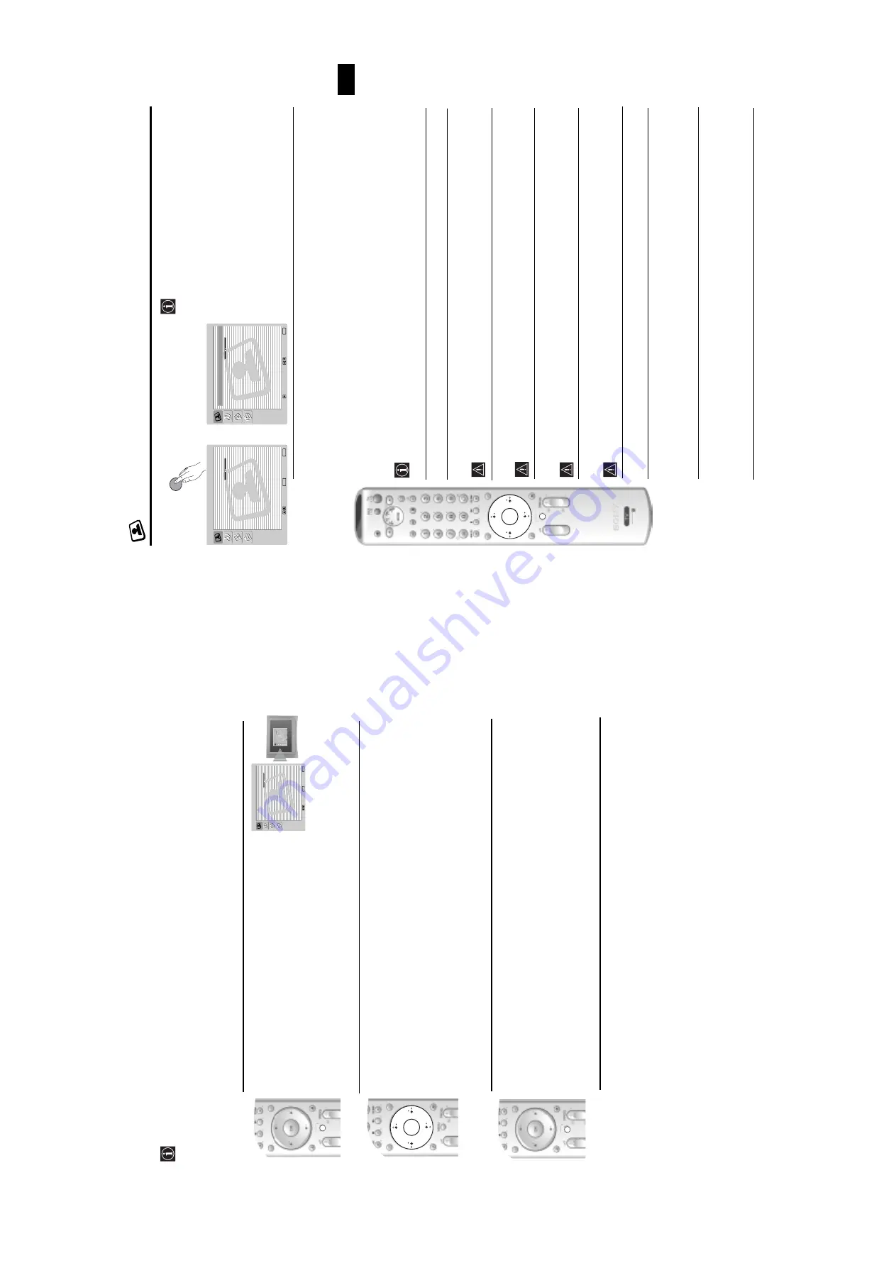
Picture  Adjustment

Select:

Enter

:

OK

Exit:

MENU

Picture Mode:

Liv

e

Contr

ast:

Reset

Noise Reduction:

A

uto

Colour 

T

one:

Cool

Picture  Adjustment

Select:

Enter

:

OK

Exit:

MENU

Picture Mode:

Liv

e

Contr

ast:

Reset

Noise Reduction:

A

u

to

Colour 

T

one:

Cool

TV 

Fun

c

ti

o

n

s

2

To

 na

v

ig

a

te

 thro

u

g

h

 the m

enu

s:

• 

T

o

 h

ig

hl

ig

h

an

d

 sel

ec

th

e

 d

esi

re

d

 m

enu

 o

op

ti

o

n

pr

ess

 v

 or


V

.

• 

T

o

 ent

e

th

sel

ect

ed

 m

enu

 or 

op

ti

o

n

press

 OK

 o

b

.

• 

T

o

 r

et

ur

n

 t

o

 t

h

la

st

 m

enu

 o

op

ti

o

n

pr

ess 

OK

 o

B

.

• To

 alter t

h

e settin

gs 

of yo

u

r selected o

p

tion

press


v

/

V

/

or


b

.

• 

T

o

 con

fi

rm 

and

 sto

re 

yo

u

sel

ec

ti

o

n

press 

OK

3

To 

switch

 off 

th

e

 m

en

u

 scr

een

s:

P

ress 

the 

MENU

 b

u

tton

 to

 re

m

o

v

e th

e

 m

en

from

 th

e sc

re

en

.

OK

MENU

MENU

11

GB

Th

Pi

c

ture A

d

ju

stment

 Menu

The

 “

P

ict

ure

 A

d

jus

tm

en

t” 

 m

en

u

 a

llo

ws

 yo

u

 to 

alter 

th

pictu

re 

setti

n

g

s.

To 

d

this:

P

ress 

the

 MENU

 b

u

tt

on 

an

th

e

n

 p

re

ss

 OK

 t

en

te

th

is 

m

en

u

Next 

p

re

ss 

v

 o

V

 t

o

 s

e

le

ct

 t

h

e


de

sir

e

d

 o

p

ti

o

an

pr

e

ss 

OK

. F

in

a

ll

re

ad

 th

e


in

stru

c

tion

s be

lo

w o

n

 h

o

w

 to

 op

er

a

te

 e

ac

h


op

ti

o

n

.

Pi

c

tu

r

Mod

e


T

hi

op

ti

o

n

 a

ll

o

ws 

you

 t

o

 cu

st

om

is

th

Pi

ct

u

re

 M

o

d

b

ased

 o

n

 t

he

 p

ro

g

ramme


yo

u

 a

re

 wa

tc

h

in

g

Afte

r se

le

ctin

g

 th

is op

tio

pre

ss 

OK

. N

ext

 pre

ss


v

 o

V


re

pe

at

ed

ly to

 se

le

c

t:   

Pe

rsona

l

 (

fo

indi

v

idua

se

tt

in

gs)

.

Li

v

e

 (for 

live 

bro

ad

cast 

prog

ramm

es,

 DVD

 a

n

d

 D

igital 

S

et 

Top

 Bo

receiv

ers)

Mo

vi

e

 (fo

r fi

lm

s).

Onc

e you

 hav

sel

ect

ed

 y

o

u

des

ir

e

d

 o

p

ti

o

n,

 p

ress

 OK

 t

o s

tor

e.

"B

ri

g

h

tn

e

ss",

 "

C

o

lo

u

r" 

an

"S

h

ar

p

n

ess"

  l

ev

el

  o

 "

L

iv

e"

 a

n

d

 "

M

o

v

ie" 

m

ode

 a

re

 f

ixed

 i

n

 th

fa

ct

ory to

 g

e

th

be

st

 p

ic

tur

q

u

al

ity

Con

tra

st

P

re

ss 

or


b

 t

o

 re

du

ce 

or 

en

han

ce 

pi

ct

u

re 

con

trast

Ne

xt

 press 

OK

 to 

st

ore

.

Brig

htness

Pr

e

ss


or


b

 t

o

 d

ark

en 

or 

b

ri

g

ht

en

 t

h

p

ic

ture

Nex

p

ress 

OK

 to 

store

.

Th

is o

p

ti

on

 o

nly a

pp

ea

rs

 for 

a

lte

ra

ti

on

 if 

"Pi

c

tu

re

 Mo

d

e

is se

t t

o

 "

Pe

rson

al".

Colo

u

r

Pr

e

ss


or


b

 to 

de

cr

e

ase

 o

r to

 in

c

re

as

co

lo

r in

te

nsit

y. 

Ne

x

t p

re

ss 

OK

 to 

st

ore

.

Th

is o

p

ti

on

 o

nly a

pp

ea

rs

 for 

a

lte

ra

ti

on

 if 

"Pi

c

tu

re

 Mo

d

e

is se

t t

o

 "

Pe

rson

al".

Hu

e

Pr

e

ss


or


b

 t

o

 d

ecre

ase 

or 

to 

inc

rease 

the

 g

reen

 t

o

nes

Nex

p

ress 

OK

 to 

store

.

T

h

is

 o

p

ti

o

on

ly 

ap

pea

rs

 f

o

r NT

S

sig

na

(e

.g

US

vi

de

ta

pes

).

Sh

a

rpn

ess

P

re

ss 

or


b

 t

o

 s

o

ften 

o

to

 sh

arp

en 

the 

p

ic

ture.

 Next 

pre

ss 

OK

 to

 sto

re

.

Th

is o

p

ti

on

 o

nly a

pp

ea

rs

 for 

a

lte

ra

ti

on

 if 

"Pi

c

tu

re

 Mo

d

e

is se

t t

o

 "

Pe

rson

al".

Rese

t

P

re

ss 

OK

 to

 re

se

th

e

 pic

tu

re

 to

 th

e

 fa

c

to

ry pr

e

se

t le

v

els.

Noise


Th

is o

p

tion

 is se

t t

o

 Au

to

 to 

a

u

to

ma

ti

c

ally re

d

uc

th

e

 s

n

o

w

y

 p

ic

tu

re

 tha

ma

y be

Red

u

c

ti

o

n


v

is

ib

le

 i

n

 t

h

br

oa

dca

st

 si

g

nal

Howe

ver

it

 can

 be 

mo

di

fi

ed

 b

p

re

ssi

ng


v

 or


V


to

 se

le

ct 

O

ff,

 Lo

w, Mi

d

 o

Hi

gh

Fi

na

ll

p

ress 

OK

 to 

st

ore

.

Colo

u

r

 T

o

n

e

Th

is o

p

ti

on

 a

llo

ws yo

u

 to 

alte

r th

e

 tin

t o

f th

e

 pic

tu

re

. Afte

r se

le

ctin

this 

op

tio

pr

es

b

Nex

press 


v

 o

V

 r

epeat

ed

ly 

to 

select: 

Wa

r

m

 (

g

ives 

th

e

 wh

ite 

c

o

lo

urs 

re

tint

), 

Nor

mal

 (

g

iv

es

 th

e

 wh

ite

 c

o

lou

rs 

ne

u

tra

tint

), 

Co

ld

 (

gi

ve

th

e

 wh

it

e


co

lo

ur

a

 blu

tin

t). 

Ne

x

t p

re

ss

 OK

 t

o

 st

or

e.

T

V

 Fun

cti

o

ns

RM-945

OK

MENU

,

Picture  Adjustment

Select:

Enter

:

OK

Exit:

MENU

Picture Mode:

Liv

e

Contr

ast:

Reset

Noise Reduction:

A

u

to

Colour 

T

one:

Cool

Pictur

e  Adjustment

Select:

Bac

k:

Enter: 

OK

Pictur

e Mode:

L

ive

Contrast:

Reset

Noise Reduction:

Auto

Colour T

one:

Cool

MENU

Summary of Contents for AE-6BA

Page 1: ...HASSIS NO KV 28FQ86B RM 945 FR SCC Q83T A KV 28FQ86E RM 945 ESP SCC Q81W A MODEL COMMANDER DEST CHASSIS NO KV 32FQ86 RM 945 KV 32FQ86B RM 945 FR SCC Q83U A KV 32FQ86E RM 945 ESP SCC Q81X A KV 32FQ86K RM 945 OIRT SCC Q82M A KV 32FQ86U RM 945 UK SCC Q84T A ...

Page 2: ...nductors 47 5 5 IC Blocks 49 6 EXPLODED VIEWS 6 1 Chassis 51 6 2 Picture Tube 52 7 ELECTRICAL PARTS LIST 53 CAUTION SHORT CIRCUIT THE ANODE OF THE PICTURE TUBE AND THE ANODE CAP TO THE METAL CHASSIS CRT SHIELD OR THE CARBON PAINTED ON THE CRT AFTER REMOVAL OF THE ANODE CAP WARNING AN ISOLATION TRANSFORMER SHOULD BE USED DURING ANY SERVICE WORK TO AVOID POSSIBLE SHOCK HAZARD DUE TO LIVE CHASSIS THE...

Page 3: ...at recovery characteristics For more information on the use of Lead Free Solder please refer to http www sony training com r e b m u n t r a P r e t e m a i D s k r a m e R 9 1 5 0 0 0 4 6 7 m m 3 0 g K 5 2 0 0 2 5 0 0 0 4 6 7 m m 4 0 g K 0 5 0 1 2 5 0 0 0 4 6 7 m m 5 0 g K 0 5 0 2 2 5 0 0 0 4 6 7 m m 6 0 g K 5 2 0 3 2 5 0 0 0 4 6 7 m m 8 0 g K 0 0 1 4 2 5 0 0 0 4 6 7 m m 0 1 g K 0 0 1 5 2 5 0 0 0...

Page 4: ... I o i d u A d n a o e d i V V T f o s t u p t u O s l a n g i s s t n e m e r i u q e R r e w o P V 0 4 2 0 2 2 n o i t p m u s n o C r e w o P W 5 0 W 0 3 1 r o t c e n n o c o r u E n i p 1 2 2 s l a n g i s o e d i V d n a o i d u A r o f s t u p n I B G R r o f s t u p n I s l a n g i s o i d u A d n a o e d i V V T f o s t u p t u O t u O r o t i n o M s n o i s n e m i D 6 8 Q F 8 2 V K m m...

Page 5: ...by a 5AMP FUSE at the distribution board e m a N l e d o M m e t I B 6 8 Q F 8 2 V K E 6 8 Q F 8 2 V K B 6 8 Q F 2 3 V K E 6 8 Q F 2 3 V K K 6 8 Q F 2 3 V K U 6 8 Q F 2 3 V K b m o C l a P F F O F F O F F O F F O F F O F F O P A P N O N O N O N O N O N O y t i r o i r P B G R N O N O N O N O N O N O x o B r e f o o W N O N O N O N O N O N O 1 t r a c S N O N O N O N O N O N O 2 t r a c S N O N O N...

Page 6: ...en 13 Ground red 14 Ground blanking 15 _ _ Red input 0 7 3dB 75 ohms positive _ S signal Chroma input 0 3 3dB 75 ohms positive 16 Blanking input Ys signal High state 1 3V Low state 0 0 4V Input impedence 75 ohms 17 Ground video output 18 Ground video input 19 Video output 1V 3dB 75ohms positive sync 0 3V 3 10dB 20 _ _ Video input 1V 3dB 75ohms positive sync 0 3V 3 10dB _ Video input Y S signal 1V ...

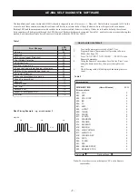
Page 7: ... the relevant device number will be displayed through the LED Series of flashes which must be counted See table 1 non fatal errors are reported using this method Each time the software detects an error it is stored within the NVM See Table 2 Table 1 How to enter intoTable 2 1 Turn on the main power switch of the TV set 2 Program Remote Commander for Operation in Service Mode See Page 22 3 Press AU...

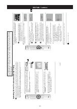
Page 8: ... and finally press the OK button to remove the diagram and continue the automatic process After the automatic tuning process has finished and any optional equipment has been connected we recommend you follow the instructions explained on the section Connection Guide on page 15 to get the optimum settings related to the optional equipment 5 The Auto Tuning menu appears on the screen Press the OK bu...

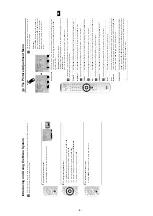
Page 9: ...films Once you have selected your desired option press OK to store Brightness Colour and Sharpness level of Live and Movie mode are fixed in the factory to get the best picture quality Contrast Press B or b to reduce or enhance picture contrast Next press OK to store Brightness Press B or b to darken or brighten the picture Next press OK to store This option only appears for alteration if Picture ...

Page 10: ...e Off TV Speakers On Headphones Set Up Select Back Enter OK MENU continued RM 945 OK MENU 19 GB RM 945 PROG 1 2 3 4 5 6 7 8 9 0 Navegador Configuración del Sistema Aceptar Versión PROG PROG Select Select Move Frame 03 Switching PAP on and off 1 Press to display PAP One of the screens will be framed to indicate that this is the active screen It means that when you want to select the PAP source you ...

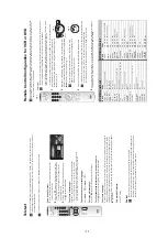
Page 11: ...ed Additional Information To do this Before you start look up the 3 digit code for your brand of DVD or VCR from the list below On those brands that have more than one code enter the first code number Sony will endeavour to update the software according to market changes Therefore please refer to the code table included with the remote control for latest code set A small label is added inside the ...

Page 12: ...ut 4 pin DIN 4 video input phono jack 4 audio input phono jacks headphones jack Sound Output 2 x 20 W music power 2 x 10 W RMS Woofer 30 W music power 15 W RMS Power Consumption KV 28FQ86U 130 W KV 32FQ86U 130 W Standby Power Consumption 0 5 W Dimensions w x h x d KV 28FQ86U approx 789 x 533 x 510 mm KV 32FQ86U approx 910 x 586 x 586 mm Weight KV 28FQ86U approx 45 Kg KV 32FQ86U approx 64 Kg Access...

Page 13: ...el Turn off any equipment connected to the Scart connector on the rear of the TV Use the menu system to enter the Language menu see page 16 and select the same language that NexTView is broadcast in Using the menu system select the Picture Rotation option in the Features menu to correct the picture slant see page 15 Using the menu system select the Manual Programme Preset menu and adjust Fine Tuni...

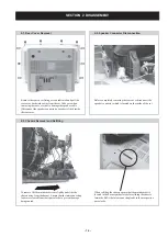
Page 14: ...revent damage being caused When refitting the chassis ensure that the main bracket is located in the beznet guide slots before sliding the chassis forwards Refit the inter connecting leads in their respective purse locks 2 3 Chassis Removal and Refitting 2 2 Speaker Connector Disconnection Remove the rear cover fixing screws indicated and pull the rear cover backwards away from the set Take care w...

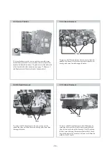
Page 15: ...he G board but with the necessity to remove only one screw from the middle of the D board Screws Clips To remove the G Board remove the two screws from the middle of the board release the clips circled and ease the board gently away from the support bracket Clips 2 4 Service Position 2 5 G Board Removal To place the chassis in the service position insert the main bracket firmly into the T slot loc...

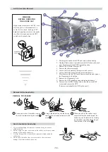
Page 16: ...ll interconnecting leads from the Deflection yoke neck assy degaussing coils and CRT grounding strap 3 Remove the C Board from the CRT 4 Remove the chassis assembly 5 Loosen the Neck assembly fixing screw and remove 6 Loosen the Deflection yoke fixing screw and remove 7 Place the set with the CRT face down on a cushion and remove the Degaussing Coil holders 8 Remove the Degaussing Coils 9 Remove t...

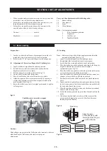
Page 17: ...o be removed This is performed by cutting the gates with a sharp wire cutter at the locations indicated by the arrows Note There are 2 plates fitted to the main bracket Only remove the necessary plate to gain access to the printed wiring board 2 REFITTING THE PLATES Because the plates differ in size it is important that the correct plates are refitted in their original location Please note that th...

Page 18: ...pe 4 Digital multimeter Fig 3 1 2 Landing Note Before carrying out the following adjustments adjust the magnets as indicated See Fig 3 4 1 Input a crosshatch signal from the signal generator 2 Rough adjust the focus and horizontal convergence 3 Switch from the crosshatch pattern to an all red pattern 4 Move the deflection yoke backwards and adjust with the purity magnet so that the red is at the c...

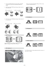
Page 19: ... corrects these areas a c d b Disk Magnets Purity control magnets GREEN BLUE RED 1 Screen centre convergence Static convergence 1 Input a dot pattern signal from the pattern generator 2 Normalize the picture setting 3 Moving vertically adjust theV STAT magnet so that the vertical red green and blue dots coincide at the centre of the screen 3 2 Convergence By opening or closing the V STAT magnet th...

Page 20: ...e section of the service menu HTIL correction can be performed by adding a THL correction assembly to the Deflection yoke C D C D C D C D R G B C D C D R G B R G B R G B VMC correction A VMC correction B THL Correction assy HAMP Adjustment HTIL Adjustment YCH Adjustment HMC correction A HMC correction B A B A B R G B R G B A B A B R G B R G B TLV Adjustment H TRAP Adjustment The H TRAP should not ...

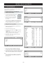
Page 21: ...isappear Layout of each control Note If you are unable to adjust the corner convergence properly this can be corrected with the use of permalloy magnets 1 Input an all white signal from the pattern generator 2 Program the Remote Commander for operation in Service Mode See Page 22 3 Enter into the Service Mode by pressing AUX VIDEO button twice and MENU on the Service Commander 4 Select Service fro...

Page 22: ...n e u q e r F t c e l e S m e t I t c e l e S u n e M s u o i v e r P t n e m t s u j d a e d o m e d i W n o i t p i r c s e D x a m n i m t l u a f e D e u l a V P M A V 7 2 1 8 2 1 5 3 5 3 M O O Z V 0 1 5 0 6 5 2 6 5 2 S O P V 1 1 5 2 1 5 0 1 0 1 N I L V 7 2 1 8 2 1 0 0 R R O C S V 0 7 2 1 8 2 1 4 4 H T D I W H 5 5 2 6 5 2 3 6 3 6 P A R T V 7 2 1 8 2 1 1 1 P M A N I P 1 1 5 1 1 5 0 8 0 8 R O C ...

Page 23: ...e M s u o i v e r P e d o m F F O E B B n o i t p i r c s e D x a m n i m t l u a f e D e u l a V F F O _ Q E R F _ W S 0 4 5 0 2 0 2 T E S F F O _ F F O _ 1 D N A B 6 9 6 9 0 0 T E S F F O _ F F O _ 2 D N A B 6 9 6 9 0 0 T E S F F O _ F F O _ 3 D N A B 6 9 6 9 0 0 T E S F F O _ F F O _ 4 D N A B 6 9 6 9 0 0 T E S F F O _ F F O _ 5 D N A B 6 9 6 9 0 0 F F O _ S S E N D U O L _ E B B 8 6 0 0 0 t c ...

Page 24: ...e p s t e S 5 0 5 6 o t e m u l o V e n o h p d a e h r e k a e p s t e S 6 0 0 8 o t e m u l o V e n o h p d a e h r e k a e p s t e S 7 0 n o e d o m g n i e g A 8 0 n o i t i d n o C g n i p p i h S 1 1 t n e m t s u j d a e r u t c i p b u S 2 1 t n e m t s u j d a r u o l o c b u S 3 1 t n e m t s u j d a s s e n t h g i r b b u S 5 1 t s e t l i o c n o i t a t o R 6 1 0 5 l e v e l e r u t ...

Reviews: