4
Figure 8
screw
screw
processor
card
screw
Figure 10
Installation—AGP Graphics and Gigabit Ethernet Models
Remove Processor Card
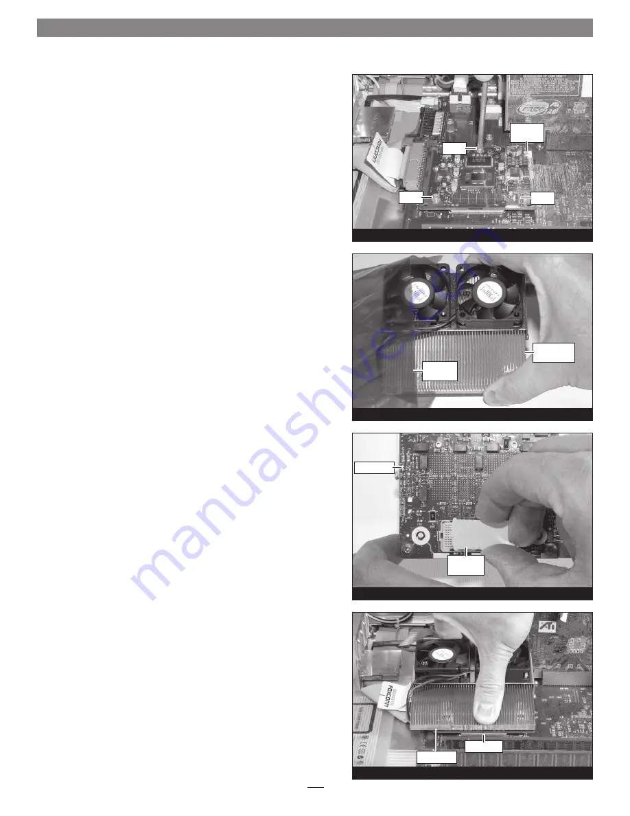
Remove the three screws securing the processor card to the logic
board
(Figure 8)
. Grasping its edges, gently lift one edge of the proces-
sor card to separate it from the logic board, and then carefully lift it
straight up and away.
Install Encore/ST G4 Duet Processor Upgrade Card
1.
Remove the Encore/ST G4 Duet processor upgrade card from
its anti-static package; make sure to handle the card by its edges
(Figure 9);
your card may differ from what is pictured.
2.
Carefully remove the cap covering the connector on the bottom
of the Duet card
(Figure 10)
, and then place the cap on the origi-
nal processor card’s connector.
3.
Place the processor card you removed from the computer into
the anti-static package, and then store it, the original heat sink,
heat sink clips, and the screws you removed in a safe place.
4.
Align the connector on the bottom of the Duet card with the
connector on the logic board
(Figure 11)
, and then set the card
down on top of the three threaded posts on the logic board (not
shown). Make sure the connectors are lined up, then, grasping
the Duet card by its heat sink, gently press it straight down until
the connectors snap together. Verify the connectors are com-
pletely coupled by gently pulling up on the edges of the Duet
board; the board should remain firmly in place.
Figure 11
protective
cap
Duet card
Figure 9
Duet card
connectors
anti-static
package
Encore/ST G4
Duet card


