


AVN-DIO09 Handbook
4
DIO Audiophile Dante® Interfaces
The DIO Audiophile Dante® Interfaces are simple plug and play audio
interfaces which provide a convenient and elegant method of connec�ng
legacy analogue and digital audio equipment to the Dante AoIP audio
network.
There are a range of different products to suit different needs and this
handbook is for the following product:
• AVN-DIO09 Microphone Input to Dante
The A/D circuitry offers a world-class E.I.N. of 129dB. All DIO products use
Dante Controller for configura�on and are powered by PoE. They use
rugged aluminium boxes with side slots for screw-moun�ng and contain
superior audio circuitry for op�mal audio performance. All feature rugged
Neutrik EtherCon® connectors and Neutrik lockable audio connectors for
ultra-reliable connec�vity.
AVN-DIO09
The AVN-DIO09 is a Microphone input to Dante converter in the Sonifex
DIO range of Dante input/output devices. It features a balanced analogue
XLR input and one Neutrik EtherCon® connector for direct connec�on to a
Dante AoIP network. Route the outputs of the DIO09 via Dante Controller.
Gain Adjustment
The AVN-DIO09 has coarse and fine mic gain. The coarse gain is set using
the toggle switch, which provides 20dB/50dB of gain. The fine gain can be
set using a trimmer adjustment tool, or small flat blade screwdriver, and
adds between 0dB and 36dB of addi�onal gain.
High Pass Filter
An on/off toggle switch turns the high pass filter on or off. When enabled,
it acts on frequencies below 125Hz at a rolloff of 6dB/octave.
Phantom Power
Phantom power is enabled/disabled via a toggle switch on the front panel.
When enabled, a 48V DC supply is provided to power an appropriate
microphone. The red LED illuminates to show phantom is enabled.
Audio Level LED
To help you to set the gain, a level LED is provided on the front panel to
display the audio level being sent to the Dante network. The indicator
thresholds are as follows:
• Off: Level is under -38dBFS (-20dBu)
• Green: Level is between -38dBFS (-20dBu) and -18dBFS (0dBu)
• Amber: Level is between -18dBFS (0dBu) and -10dBFS (+8dBu)
• Red: Level is above -10dBFS (+8dBu)
N.B. If using a phantom powered microphone, it may be necessary to
earth the unit using the rear panel earth tag to eliminate mains hum.
Fig 1-1: AVN-DIO09 Front and Rear View
Setup
The DIO Dante device is configured with a dynamic network address, so to
ini�ally get the unit working, connect it to a network with a DHCP server
(such as a router) and a suitable IP address will be given to the unit. Once
connected, a different IP address can be given to the DIO using Dante
Controller. See the following sec�on on Network Troubleshoo�ng if you’re
having problems connec�ng your DIO device.
Simply plug an Ethernet connector into the Ethernet port of the DIO and
the other end of the Ethernet connector into a PoE enabled switch.
Alterna�vely, if the switch doesn’t support PoE, a PoE adaptor can be used
to provide the power.
The audio inputs/outputs should be connected to the legacy equipment
and this allows the legacy equipment to transmit audio and receive audio
through the Dante® network.
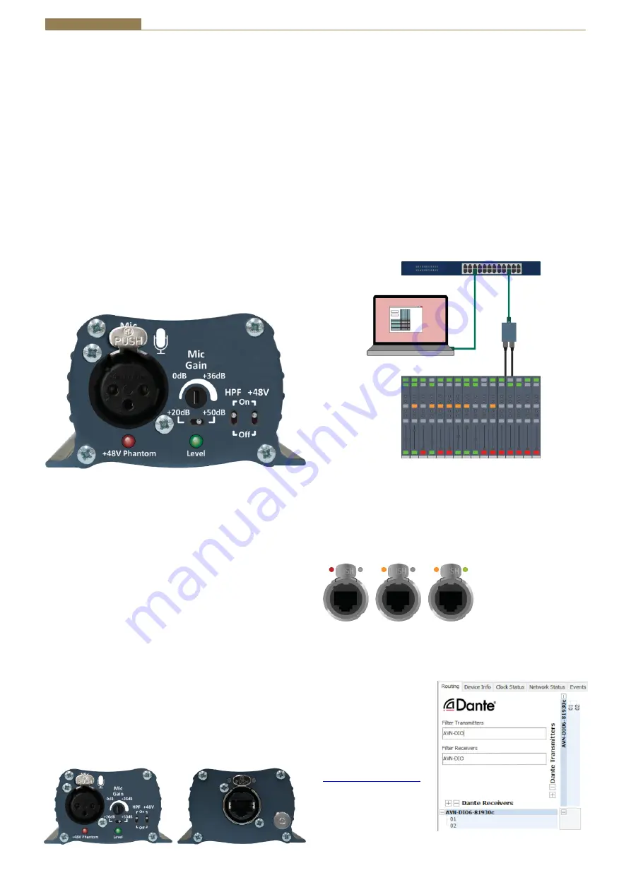
A computer on the Dante® network can then configure connec�ons
between the DIO and other Dante® enabled devices, using Dante Controller.
Fig 1-1: Setup
Link
Link status is indicated using the top-le� status LED. Once power has been
supplied to the unit the link status LED turns red. The link status LED turns
amber when a link is established with a link speed of 100 Mbps.
Link ac�vity is indicated using the top-right status LED which blinks when
data is incoming, or when outgoing data is sensed on the port.
Fig 1-2: Power, Link, and Ac�vity LEDs
Dante Controller
Once a link has been
established Dante Controller
can be used to configure the
device. Dante Controller is an
applica�on provided by
Audinate and can be
downloaded from their
website.
Within Dante Controller the
unit should be visible within
the Rou�ng tab.
Fig 1-3: Rou�ng
PC Running
Dante
Controller
Analogue/Digital
Legacy
Equipment
Network
Switch
AVN-DIO
Audio
Network


