©Copyright 2010-Sonic Air Systems Inc.
Page
15
of
26
3.1
Tools required
- 1-1/8 in. open wrench (used at jackscrew hex nut)
- 3/4 in. open wrench (used at blower pad hex screws)
- 15/16 in. socket wrench (used at bracket to motor hex nuts)
- 3/4 in. socket wrench (used at blower pad hex nuts)
- cross-recessed (Phillips) screwdriver (used at belt guard screws)
- 1/4 in. allen wrench (used at blower sprocket/bushing assembly)
- 5/16 in. allen wrench (used at motor sprocket/bushing assembly)
- 5/32, 1/8 and 3/16 in. allen wrenches (for bushings)
- 0.025 or 0.050 in. thk. Stainless steel slotted shim with slot for 5/8” bolt
- Straight Edge 3 ft. long (used at sprocket alignment and belt tension check)
- Sprocket Installation Tool (Sonic P/N 12816)
- 9/16 in. socket wrench (blower and motor sprocket screws)
3.2
Read all safety procedures (see page 3) before starting any of the following steps.
3.3
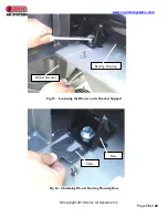
Remove belt guard by loosening the six cross-recessed head screws holding it to the structure. Slide
the belt guard away from the structure – see Fig.7.
3.4
The alignment verification is done with the 3’ straight edge on the left and right side of sprocket
faces relative to shafts. Perfect alignment is the situation achieved when good contact exists between
straight edge and the faces of the sprockets on each side of the shafts (see Fig.12).
Adjustment for misalignment should be done either by modifying motor sprocket position along
motor shaft (when sprocket face planes are offset relative to one another) or by modifying blower
position (when sprocket face planes are rotated relative to one another). All alignment adjustments
are done with the belt removed.
Offset misalignment
(see Fig.11)
–
the straight edge either interferes equally with blower sprocket on both sides of blower shaft or
there is an equal gap between straight edge and the face of the blower sprocket on both sides of
blower shaft.
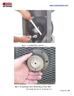
-To correct offset misalignment, the motor sprocket / QD bushing assembly must be slid on
the motor shaft to the correct position. To slide the QD bushing, it is first necessary to
disassemble the sprocket by removing the 3 hex head cap screws that hold it to the hub (see
Fig.13); afterwards, install the screws into the three threaded holes of the sprocket and by
turning the screws, the sprocket will be jacked away from hub. Use the sprocket installation
tool for the above operations to prevent sprocket from rotating. Have the tool located into
two of the three holes available on the sprocket (see Fig.13). Slide the QD bushing to the
proper position by aligning the sprocket faces using the straight edge (see Fig.14). Tighten
bushing set screw to 5-7 ft-lbs. After QD bushing relocation, proceed with sprocket
reinstallation. Recheck misalignment and correct as necessary following the same procedure.
Tighten motor sprocket screws to bushing to 30 ft-lbs.