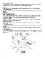
Sonetics SON200 Installation & Operation Manual Download Page 17


16 

SYSTEM TEST 

This procedure tests all functions of the SON200 Series Intercom System and is used to test the system for proper 

operation after installation. In the event of a system failure, it may be used to identify exact symptoms before 

troubleshooting a problem, and to test the system after repair work has been performed. 
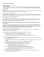
POWER ON:


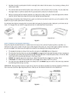
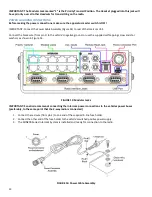
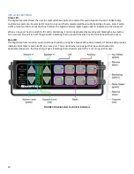
Turn on the apparatus master switch, and confirm that power is applied to the intercom by observing that at least one 

Volume Indicator LED (Figure 20) is lit. Using the Up and Down Buttons, adjust the Volume Control (Figure 20) to the 

middle of its range. 

TEST INTERCOM OPERATION:


1.


Plug a headset into the appropriate Headset Module.  

2.


Turn the headset Volume Control all the way down (counterclockwise).  

3.


Put a headset on your head and adjust the headband/headstrap for a comfortable fit.  

4.


Adjust the mic boom to place the microphone in front of your mouth and approximately 1/8” from your lips.  

5.


Speak into the mic to confirm intercom operation. You should hear yourself through the headset speakers.  

6.


Refer to your Headset User’s Guide to determine how to activate the microphone. 

7.


Turn the headset Volume Control fully clockwise. 

8.


While speaking into the microphone, adjust the volume control on the intercom unit slightly louder than a 

comfortable listening level.  

9.


Adjust the headset volume for a comfortable listening level.  

10.


Monitor radio communications. Verify that the incoming radio transmissions are the same volume as the 

intercom volume.  

11.


Repeat steps outlined in “

Test Intercom Operation

” for each headset/headset position on the apparatus.  

TEST RADIO COMMUNICATION


IMPORTANT: The next 4 steps are for Radio-Transmit Headsets only! These are the BEHIND-THE-HEAD, -51 Series 

models and OVER-THE-HEAD, - 51 Series models, and have a red PTT on the ear dome. 

1.


Put on a Radio-Transmit Headset (Behind the Head or Over the Head headset, red PTT models).  

2.


Confirm radio transmission by pressing the red PTT button on the ear dome and speaking into the microphone. 

3.


If using a foot switch; test radio transmission by pressing the foot switch and speaking into the microphone on 

the headset.  

4.


Repeat steps outlined in “

Test Radio Communication

” for each Radio-Transmit Headset on the apparatus.  

SYSTEM DYNAMIC TEST


1.


Start the apparatus engine.  

2.


Using a Radio-Transmit Headset close to the intercom unit, check the intercom and radio functions.  

3.


Final adjustment of the Volume Controls may be required under actual apparatus operating conditions. 

IMPORTANT: If excessive engine/siren noise is present in the headsets, the intercom volume level should be reduced 

slightly. To compensate for this reduced volume, you must speak louder into the microphone. 

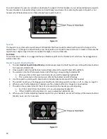
REMOTE INTERCOM TEST


1.


Press the Volume Up and Down arrow. Note the same changes on the base unit.  

2.


Press the radio select buttons. Note the same changes on the base unit.  
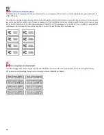
HEADSETS 

Sonetics offers many styles of headsets for use with SON200 Series Intercoms. Headsets are available in an Over-The-

Head, or Behind-the-Head style. Either of these styles can be Radio-Transmit capable, or Intercom-Only

.

  For more 

information regarding the different models of headsets available, contact your local Sonetics Dealer

.


RADIO-TRANSMIT HEADSETS


The Radio-Transmit Headsets receive both intercom and radio communications at all times. The mic is always active for 

intercom communications. Radio-Transmit Headsets are typically used at the Driver position. 

Summary of Contents for SON200

Page 1: ...SON200 Series Digital Intercoms SON201 SON202 SON203 SON204 Series Digital Intercoms Remote Intercoms Installation Operation Manual...

Page 2: ...REAR PANEL 6 PRE INSTALLATION 7 INSTALLATION 11 SYSTEM TEST 16 INTERCOM OPERATION 17 PROGRAMMING INPUT AND OUTPUT DEVICE GAIN 17 MODULAR PLUG INSTALLATION 21 TROUBLESHOOTING 22 ADVANCED TROUBLESHOOTIN...

Page 3: ...on Waterproof remote intercom head for outdoor installations Each crew member will hear all radio traffic and be able to communicate over the intercom Crew members wearing Radio Transmit headsets may...

Page 4: ...tact your local Sonetics Dealer for more information regarding an Interface Cable specific to your radio POWER CABLE ASSEMBLY Provides the power connections for the SON200 Series Intercom Unit The pow...

Page 5: ...microphone volume and sensitivity for various ambient background noise levels RADIO INTERFACE PORT A 9 pin D sub jack on the rear of the Intercom RADIO INTERFACE CABLE The cable which plugs into the...

Page 6: ...H LEVEL DOWN BUTTONS 10 red LED s which indicate the master volume level setting There are 3 volume changes between lights RADIO SELECT LED BUTTONS Green LED o The green LED indicates which radio is t...

Page 7: ...e the Power Cable Assembly is plugged in to interface the SON200 Series Intercom to the vehicle s power supply MODULAR JACKS The modular jacks are the connection points for the CA Cables leading from...

Page 8: ...ear of the intercom unit for service and installation The Digital Intercom should be placed where it will be easy to route all the CA Cables from the Headset Modules The Digital Intercom should be pla...

Page 9: ...a method used to increase the number of headset positions available or a method of reducing the number of cable runs and the length of the cable runs Daisy Chaining the Headset modules is easy to acco...

Page 10: ...e intercom and radio communication to the headset positions REMOTE MODULAR JACKS On the rear of the intercom there is 1 modular jack under REMOTE Figure 4 This jack is for connecting CA Cables for the...

Page 11: ...ed radio technician Contact your local Sonetics Dealer for more information regarding the availability of an interface cable for your radio If a radio specific cable is not available for a particular...

Page 12: ...r obstructions that could be damaged while drilling the holes Install the mounting bracket with the sheet metal screws Figure 8 Remove the 4 screws 2 on each side closest to the rear of the intercom u...

Page 13: ...dset Module to the Intercom it MUST be inserted into the Modular Jack on the same side of the HM 10 as the Sonetics label If the CA Cable is part of a daisy chain you will need to remove the plastic t...

Page 14: ...m pin 1 to the vehicle s negative ground or use the supplied self tapping screw and star washers as shown in Figure 14 FIGURE 13 Modular Jacks IMPORTANT Sonetics recommends connecting the intercom pow...

Page 15: ...al Sonetics Dealer Plug the 9 Pin plug on the end of the MR 0X Mobile Radio Interface Cable into the desired Radio Interface Jack on the rear of the intercom Figure 15 IMPORTANT Tighten the 2 screws o...

Page 16: ...heet metal screws 4 making sure the cable is not pinched Recommended torque 10 in lbs 5 Determine the correct length for the CA cable and cut cable to correct length Mounting with Bracket part number...

Page 17: ...TION IMPORTANT The next 4 steps are for Radio Transmit Headsets only These are the BEHIND THE HEAD 51 Series models and OVER THE HEAD 51 Series models and have a red PTT on the ear dome 1 Put on a Rad...

Page 18: ...just the Receive Audio Adjustment or the radio s volume control INTERCOM ADJUSTMENTS AND OPERATIONS For the Radio Aux and Cell connections to the intercom the user can adjust input gain and output gai...

Page 19: ...Squelch up and Squelch down buttons for 5 seconds FIGURE 19 2 Once squelch control mode has been successfully entered the squelch level LEDs will flash 3 You will also note that the lowest volume LED...

Page 20: ...is the transmit radio This radio will be used when any user presses the PTT button on their headset To select another radio as the transmit radio simply press the button that corresponds to that radio...

Page 21: ...too much traffic and is distracting it can be deactivated by pressing and holding the Aux button for 3 seconds This will turn off the green LED indicating that no audio from that Aux Port will be hea...

Page 22: ...ug into the plug holder on the crimping tool labeled D in Figure 21 until the release tab on the plug locks into position 7 Holding the cable so that the printed side of the cable is toward the releas...

Page 23: ...the Advanced Troubleshooting procedures on pages 24 25 ALTERNATOR WHINE OTHER DISTRACTING NOISES Because of the level of ambient noise present with the apparatus motor running alternator whine and oth...

Page 24: ...Make sure it is not turned all the way down If there is no audio from the radio s speaker o Disconnect the Radio Interface Cable from the radio If there is audio from the radio s speaker the Radio Int...

Page 25: ...or unplugging a headset when not in use Unplug the headset locations one at a time from the rear of the Intercom Unit until the squeal stops Check the headset configuration for faulty connections or c...

Page 26: ...25 WIRING DIAGRAM SCHEMATICS...

Page 27: ...26 Wiring Diagram Schematics Headset Module Wiring Remote Head Wiring...

Page 28: ...ohms Output Voltage 370 mV 114 SPL re 0002 microbar Frequency Response Optimized for speech clarity and noise reduction Max Am Noise Level 125 dB SPL re 0002 microbar Weight 0 2 oz INTERCOM Size 6 6 L...

Page 29: ...676 00 HANDHELD RADIO INTERFACE Works with all Sonetics headsets Contact your Sonetics Dealer for specific information regarding your particular handheld radios MIC MUFFS DOZEN Replacement mic muffs w...

Page 30: ...ency energy and if not installed and used in accordance with the instruction manual may cause harmful interference to radio communications Operation of this equipment in a residential area is likely t...

Page 31: ...tative of Sonetics or an Sonetics Authorized Service Provider f to a product or part that has been modified without the written permission of Sonetics g if any Sonetics serial number has been removed...

Page 32: ...service soneticscorp com 2019 Sonetics Corporation All rights reserved The information in this document is subject to change without notice No part of this document may be copied or reproduced in any...

Reviews: