-6-
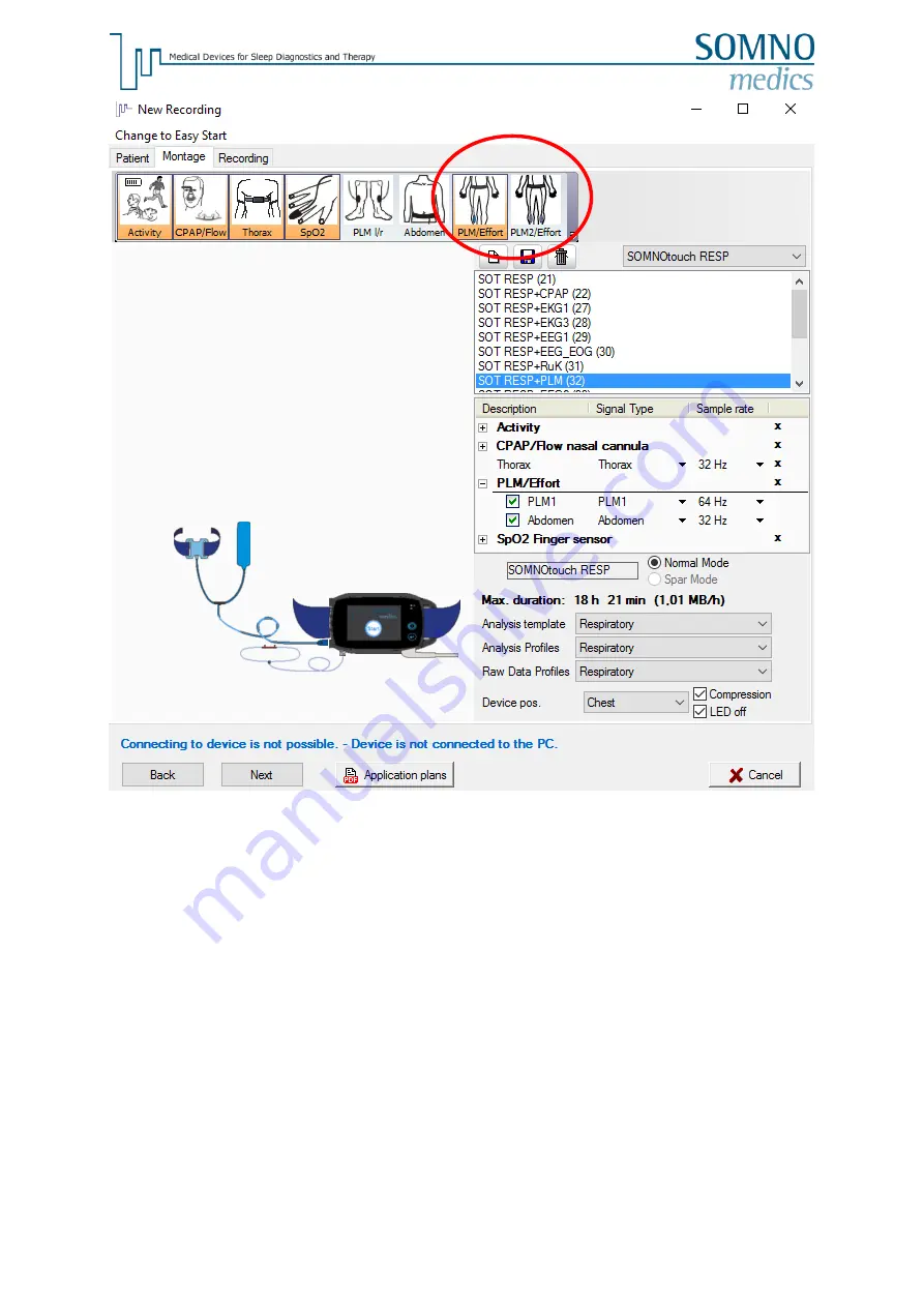
Figure 4. Adjustment of the montage - 3.
Please proceed then with the initialisation as usual.
or:
Page 1: ...1 SOMNOmedics GmbH Am Sonnenstuhl 63 D 97236 Randersacker Tel 49 931 35 90 94 0 Fax 49 931 35 90 94 49 E Mail info somnomedics de Internet www somnomedics eu SOMNOtouch RESP PLM INSTRUCTION MANUAL...
Page 2: ...nnenstuhl 63 65 D 97236 Randersacker Tel 49 931 35 90 94 0 Fax 49 931 35 90 94 49 E Mail info somnomedics de Internet www somnomedics eu Rev 1 08 06 2016 All proper names marked with TM are copyright...
Page 3: ...ensors 7 3 1 Applying the sensor using the 2PLM sensor Art No TOS110 7 3 2 Applying the sensors using the Effort 1PLM Combi Sensor Art No TOS140 7 3 3 Applying the sensors using the Effort 2PLM Combi...
Page 4: ...efer to the safety notes in the main manual of the SOMNOtouchTM RESP Device and sensors may not be used in live sustaining or life supervising measures 2 Initialisation 2 1 Initialisation using SOT RE...
Page 5: ...g on your sensor pack Figure 2 Adjustment of the montage 2 Clicking on Add Delete sensors opens a list of available sensors for your SOMNOtouch RESP Figure 2 The sensors PLM Effort or PLM2 Effort can...
Page 6: ...6 Figure 4 Adjustment of the montage 3 Please proceed then with the initialisation as usual or...
Page 7: ...sor applications Figure 5 Applying the 2PLM sensors and connecting them to the SOT RESP 3 2 Applying the sensors using the Effort 1PLM Combi Sensor Item No TOS140 Connect three PLM electrodes e g SEN0...
Page 8: ...below Fix the cables with adhesive tape for strain relief to ensure stable recordings Figure 5 Plug the cable of the PLM sensors in the AUX socket of the effort belt Now plug the cable of the effort b...
Page 9: ...ters for the analysis the colour display of the analysis curves and the colour classification of the events click at the colour field red frames in the figures The analysis source is shown down right...
Page 10: ...ratio will be detected as a Leg Movement 4 Min Duration ms Minimum duration of a Leg Movement event 5 Max Duration ms Maximum duration of a Leg Movement event 6 Connection time ms Two PLM events duri...
Page 11: ...rrelation s The correlation between a LM event and a Body Position Change can be scored The delay between the 2 events can be set here It will indicate the maximum time interval between the LM event a...
Page 12: ...t Definitions Total LMs Index Total number of Leg Movements during TIB Isolated LMs Index Leg Movements during TIB which do not meet the PLM criteria Index per hour of sleep PLMs Index Leg Movements d...
Page 13: ...ase is of Type 1 PLM s occur mainly in the first third of sleep or Type 2 PLM s occur mainly in the last third of sleep Utilising this information allows for the selection of adequate drugs with appro...