
GRW
Installation
7
SolutionAirGroup.com
|
GRW - Manual
8. Fuses are furnished and installed by the factory in
accordance with the National Electrical Code, ANSI/
NFPA 70, and /or the Canadian Electrical Code, CSA
C22.1. If replacement of any fusing is necessary, the
replacement MUST be of the same amperage as the
original. Failure to use equivalent replacement fuses
may result in damage to components within the
electrical system of the unit and/or the building. If any
of the original wires need to be replaced, they must
be replaced with type TEW 105° or equivalent except
where noted.
9. On units with three-phase power supplies, make sure
that motor rotation is correct as connected.
Auxiliary Power Connections
A separate 120/1/60 power supply may be required on
units with convenience outlets and lights. Refer to unit
wiring diagrams for wiring sizing details and connection
points.
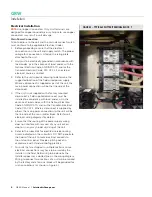
Control Installation
All field wiring must be in accordance with local codes, or
in the absence of local codes, with the National Electrical
Code, ANSI/NFPA 70, and/or the Canadian Electrical Code,
CSA C22.1.
Control wiring will depend on the controls provided with
the unit. A controller is provided with the unit unless
otherwise specified in the submittal documents. Refer to
unit electrical wiring diagrams for details.
Control Connections
Units supplied with controllers may require field-wiring to
a remote sensor or control panel. Refer to unit electrical
wiring diagrams for details.
An optional space thermostat or sensor may be shipped
loose for field installation. The sensor may be duct
mounted and/or wall mounted.
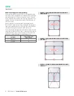
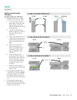
1. Locate space sensors or thermostats where they
will provide a representative reading of the space
condition.
2. Avoid areas with cold drafts or in the warm supply-air
stream of the unit.
3. On indoor units, do not mount the thermostat or
sensor on the unit casing, as it may be affected by heat
radiating off the unit.
4. Do not place near other sources of warmth, such as
lamps, appliances, etc.
5. Refer to unit electrical wiring diagrams for details on
how to wire the sensor to the control panel.
6. Ensure that all remote wiring is equivalent to factory
installed wiring and that voltage drop does not exceed
10 percent.
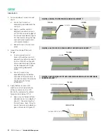
An optional duct mounted discharge air temperature
sensor may be shipped loose for field installation.
1. The sensor strip must be parallel to the flow of air.
2. The sensor must be mounted as close to the center of
the duct as possible.
3. The sensor must be located in a straight section of the
duct and must be 8-10 feet (2.4 to 3m) downstream
from the supply air connection.
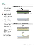
4. Do not install temperature sensors near any elbows or
transitions.
5. Refer to unit electrical wiring diagrams for details on
how to wire the sensor to the control panel.
6. Ensure that all remote wiring is equivalent to factory
installed wiring and that voltage drop does not exceed
10 percent.
An optional remote control panel may be shipped loose for
field installation.
7. Locate the indoor panel where operation and
maintenance personnel have ready access.
8. Follow the manufacturer’s installation instructions.
9. Refer to unit electrical wiring diagrams for details on
how to wire the sensor to the control panel.
10. Ensure that all remote wiring is equivalent to factory
installed wiring and that voltage drop does not exceed
10 percent.
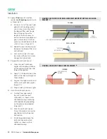
Where possible, the low limit temperature sensor is factory
mounted. Some unit configurations require the sensor
to be field mounted in the supply air ductwork. In this
situation, the sensor and field wiring will be coiled up in the
weather housing. The installing contractor shall install the
sensor approximately 10 ft. (3 m) down the supply air duct.


