


4
5
.&/6
&4$
ⶸ
ⶼ
ⶾ
ⶺ
4&5
183
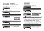
② Status Indicating light
Name for each part
Top side
Bottom side
① Folding antenna: 180 degree rotation and angle
adjustment can be done.
⑤ User setting button
③ Bracket fixing hole
④ Set screen window
⑥ Adapter Input: DC12V 1A
(Please be sure to use the adapter
provided with the product.)
Adapter is one of expendable supplies.
When necessary, please purchase an adapter with DC12V 1A
PWR
Red light when the power is on
RX
Waiting for reception : Red light flashing
TX
During transmission : Red light flashes and
then light off
MENU
ESC
·Menu button for setting mode
·English/ numeric change button
▲ ▼ ·Up/Down direction button
◀ ▶ ·Left / Right direction button
SET
PWR
·set value saving button
·Power ON/OFF button
DC12V 1A
[Picture of bracket mounting]
[Back side cover]
Type of set mode
User can set following modes with user set button.
E1 FrEq
Frequency setting
The function to set the frequency of the repeater.
E2 rEgT
Call bell ID registration
The function to register the ID of the call bell to be relayed.
E3 dUPT
Setting of the time for prevention of duplicate reception
(Default setting is 5 seconds)
The function to restrict reception for call from the same call bell.
E4 TXdT
Transmission delay time setting (TX Delay Time)
The function to set the delay time of the transmission after receiving call.
E5 dELE
Individual deletion of the call bell ID
The function to delete registered call bell individually.
E6 NOrX
[No Receive] bell ID setting
The function to set the call bell which user does not want to receive among
the registered call bells.
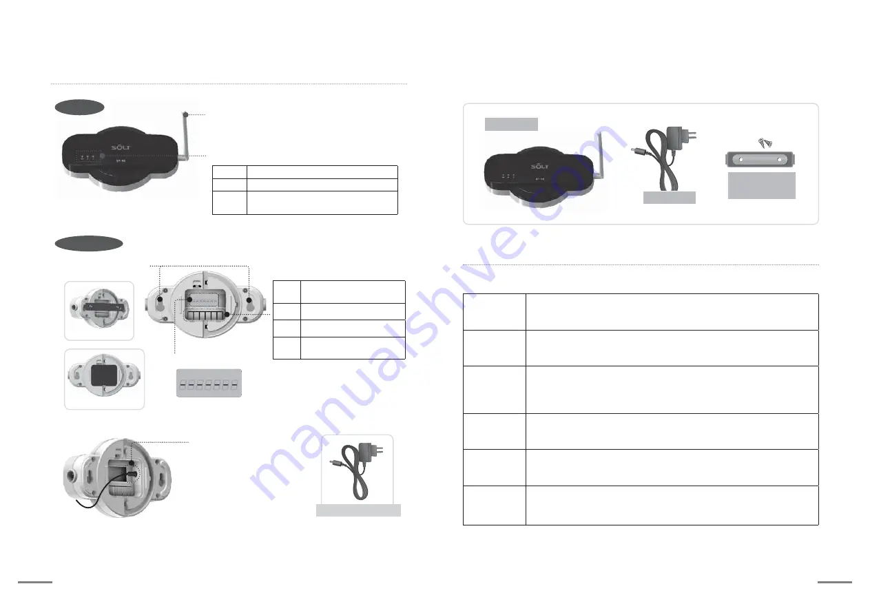
Main body
Components
Adapter
Bracket
(with 2 screws)