background image

PVI 3000S, 4000S, 5000S, 5300 Series Inverters       


Installation and Operation Manual (Rev A) 


60 

Preparing the product for shipping: 

1) 

Package the unit safely, preferably using the original box and packing materials. Please 
ensure that your product is shipped fully insured in the original packaging or equivalent. 
This warranty will not apply where the product is damaged due to improper packaging. 

2) 

Include the following: 

a. 

The RMA number supplied by Solectria Renewables clearly marked on the outside of 
the box. 

b.  A return address to which the unit can be shipped. Post office boxes are not 

acceptable. 

c.  A contact telephone number where you can be reached during work hours. 

d.  A brief description of the problem. 

Ship the unit prepaid to the address provided by your Solectria Renewables’ customer service 
representative. 

Returning a product from outside of the USA or Canada: 

In addition to the above, you MUST include return freight funds and are fully responsible for all 
documents, duties, tariffs, and deposits. 


Contact information: 
Solectria Renewables LLC 
360 Merrimack Street, Building 9 
Lawrence, Massachusetts, 01843 
USA 
 
Tel:  978.683.9700 
Fax:  978.683.9702 
Email: 

[email protected]


Website: 

www.solren.com 


Summary of Contents for PVI 3000S

Page 1: ...S PVI 4000S PVI 5000S PVI 5300 INSTALLATION AND OPERATION MANUAL Revision A Residential Commercial Grid Tied Photovoltaic Inverter 2012 Solectria Renewables LLC All information subject to change without notice ...

Page 2: ...stallation and Operation Manual Rev A IMPORTANT REGISTRATION AND WARRANTY INFORMATION For warranty to become active this inverter must be registered To activate warranty and register inverter please visit the link below www solren com registration ...

Page 3: ...educe the risk of electrical shock and to ensure the safe installation and operation of the inverter the following safety symbols are used to indicate dangerous conditions and important safety instructions WARNING This indicates a fact or feature very important for the safety of the user and or which can cause serious hardware damage if not applied appropriately Use extreme caution when performing...

Page 4: ...stallation électrique doivent être exécutés en conformité aux normes électriques locales ainsi qu à la norme nationale américaine et canadienne Le PVI 3000S PVI 4000S PVI 5000S et PVI 5300 ne contient aucune pièce requérant un entretient effectué par l utilisateur Pour toute maintenance veuillez consulter Solectria Renewables ou un installateur agrée par Solectria Renewables les coordonnées de Sol...

Page 5: ...ection of Communication Wiring 31 4 5 Communication ID Adjustment 33 5 0 Commissioning the Inverter PV System 33 5 1 Turning on the Inverter 34 5 2 Operation 34 5 3 Turning off the Inverter 34 6 0 LCD Display LED Indicators Errors and Messages 34 6 1 LCD Display 35 6 2 LED Indicators 36 6 3 LCD Display Messages 37 7 0 Troubleshooting and Inverter Messages 48 7 1 Inverter Messages 48 7 2 Maintenanc...

Page 6: ...10 3 Appendix C Contact Information 64 10 4 Appendix D Authorized Distributors 64 10 5 Appendix E Positive Grounding Option 64 10 6 Appendix F Weatherproof Shield for Wind Driven Snow and Rain 67 10 7 Appendix G PVI 3000S 5300 PV Inverter Fault Report Form 68 10 8 Appendix H UL1741 IEEE 1547 CSA22 2 107 1 Listing Letter 69 ...

Page 7: ...stitutional facility s electrical system that is connected to the electric utility grid The inverters are not capable of feeding currents back into the PV array from the AC source which include short circuit s or fault s in the PV array or string s If the PV system and inverter are providing the same amount of electrical power that the facility is using then no power is taken from or fed onto the ...

Page 8: ...splay is only possible when the Inverter is in operation An optional full featured inverter direct data acquisition and data logging gateway and web based service is available from Solectria Renewables LLC called Solrenview http www solrenview com You have the option to purchase the gateway which plugs into the inverter and to the facility s internet service Technical structure of the PVI 3000S PV...

Page 9: ...the grid is back to normal The display then shows Monitoring Disconnecting from the grid is important to protect the line workers who may be working to restore the grid as well as electricians working at a site with PV systems Power grid faults that will cause the PVI 3000S PVI 5300 to isolate itself from the power grid AC grid voltage The grid voltage must not go outside the range of 12 10 of the...

Page 10: ...ack 2 PV array ground fault interrupt GFDI fuse 3 DC AC disconnect 4 DC knockouts bottom side and back 5 Fan assembly on back at bottom of heatsink used on PVI 4000S 5000S 5300 only 6 RS 485 interfaces 7 LCD display 8 LED indicators for basic operating status 9 Inverter Serial Number 10 Detachable wiring box 11 Quick mount wall plate behind unit 7 5 3 4 2 8 11 9 10 1 6 ...

Page 11: ...necessary For optimal electrical system efficiency use the shortest possible AC and DC cables and use the maximum allowable cable size Avoid installation in close proximity to people or animals as there is an audible high frequency switching noise Install the inverter in an accessible location following local codes Note that code requirements for clearances and proximity to other equipment and bui...

Page 12: ... and the manner in which it is connected to the utility grid See NEC Article 690 for guidance within the US The cooling air enters at the bottom of the heat sink and exhausts at the top of the unit See Figure 2 1 3 for recommended clearances for cooling air and space around the inverter If you are installing the inverter in a utility vault or electrical closet the air circulation must be sufficien...

Page 13: ...and Operation Manual Rev A 13 2 1 Inverter Positioning and Mounting Correct mounting position for the inverter is vertical with back of inverter mounted to a wall Figure 2 1 1 PVI 3000S 4000S Dimensional Diagram Figure 2 1 2 PVI 5000S 5300 Dimensional Diagram ...

Page 14: ...gure 2 1 3 Inverter clearances WARNING Severe injury or death could occur if the inverter mounting fails and the unit tips over or falls on a person NOTE The weight of the inverter will exert an added load to the wall where mounted Be sure to verify proper load capacity of mounting surface ...

Page 15: ...ked and tested before it is shipped Even though it is packaged in a rugged cardboard box the inverter can be damaged during shipping by poor handling trucking or transfer station activity Please inspect the inverter thoroughly after it is delivered If any damage is seen please immediately notify the shipping company to make a claim If there is any question about potential shipping damage contact S...

Page 16: ...he inverter may tip over if improperly moved potentially causing damage to equipment personal injury or death After taking the inverter out of the cardboard box you will find the mounting bracket in the bag behind the heatsink First the mounting bracket needs to be picked up from the inverter as shown in Figure 3 2 1 Figure 3 2 1 Remove mounting bracket from Inverter ...

Page 17: ...e mounting bracket as a template to mark the locations on the wall where holes should be drilled After drilling the holes the mounting bracket should be fastened to the wall with screws or screw anchors The height of the anchor head 8mm Figure 3 2 3 Fastening the Mounting Bracket 1 4 diameter mounting screw recommended or 3 16 1 4 anchor bolt ...

Page 18: ...t and slipped down into place Make sure the lower lip on the bracket hooks into the window on the back of the inverter as shown in Figure 3 2 4 120cm 47 100cm 39 flange with mounting slots Ground Floor Ground Floor Slide the mounting hooks on the inverter over the hooks on the mounting bracket Ensure the inverter is seated properly on the mounting bracket Figure 3 2 4 Mounting Inverter onto the Mo...

Page 19: ...rters Installation and Operation Manual Rev A 19 After the inverter is hooked properly on the bracket secure it with screws at the bottom flange as shown in Figure 3 2 5 Figure 3 2 5 Fasten the Inverter with the screws at the bottom flange ...

Page 20: ...any time Note that this is reversed for systems using the positive grounded option AC and DC PV Connections The PVI 3000S 5300 inverters are equipped with covered holes and knockouts to fit conduit fittings that are NEC code compliant for use with several sizes of rigid and flexible metallic or non metallic conduit All conduit and wiring installation is done in the wiring box This design allows in...

Page 21: ...ll be no damage from lightning they can help prevent or limit potential damage Grounding Electrode Conductor As with all PV systems a Grounding Electrode Conductor must be installed per NEC 690 47 and 250 166 This conductor should be sized according to these NEC requirements This conductor should be terminated on the labeled ground point located at the bottom of the wiring box where the DC and AC ...

Page 22: ...rically safe working conditions WARNING Follow PV module manufacturer s installation directions PV arrays produce electrical energy when exposed to light and could create a hazardous condition Disconnect array conductors when wiring the inverter or cover the array with an opaque material prior to wiring WARNING Before connecting the connectors of the PV module to the DC inverter terminals check th...

Page 23: ...0S 4000S 5000S 5300 Series Inverters Installation and Operation Manual Rev A 23 ON OFF Figure 4 1 1 Turn the DC AC Disconnect Switch off Figure 4 1 2 Remove the 4 Screws on the Wiring Box and Remove the Cover ...

Page 24: ...the box into the wall for a hidden wiring installation Figure 4 1 3 Punch Out the Knockouts where the Conduits will enter the Wiring Box The following three sections describe the wiring for the AC DC and communication ports The AC and DC wiring shall be done in the wiring box of the PVI 3000S 4000S 5000S 5300 There are a pair of DC terminal blocks a DC fuse a bypass terminal block two 2 RJ 45 conn...

Page 25: ...ection without a neutral The utility configuration jumpers J210 are located on the control board as shown in Figure 4 1 5 are used to set the PVI 3000S 5300 inverter to be connected to the commonly used utility configuration types shown in Figure 4 1 6 As shown in Figure 4 1 5 the P1 and P2 pins are used to configure the PVI 3000S 5300 inverter for the connection types of 208V and 240V AC outputs ...

Page 26: ...PVI 3000S 4000S 5000S 5300 Series Inverters Installation and Operation Manual Rev A 26 P1 P2 P3 J210 P2 P3 P1 Figure 4 1 5 Building Utility Configuration Jumpers ...

Page 27: ...ty is switched OFF before connecting the power wires from the breaker to the inverter AC terminal block Use 10 AWG to 6 AWG 90 C 194 F copper wire for all AC wiring connections to the PVI 3000S 5300 inverters You must choose the appropriate wire size based on local code requirements Designed voltage drop recommended to being no greater than 1 Larger conductors will be needed for longer wire runs ...

Page 28: ...ne1 of the AC terminal block Connect the L2 wire to the terminal labeled Line2 of the AC terminal block Tighten the screws with a torque of 15 6 in lb 1 7Nm Reconfirm that all connections are correct as described above and all screws are properly tightened WARNING Each connection to a PVI 3000S 5300 inverter must be installed with a dedicated circuit breaker No other appliances may be connected to...

Page 29: ...nnected in parallel when more power is needed In the parallel configuration each inverter shall connect to its own PV array Do not connect one PV array to more than one inverter This will cause the inverter to function abnormally Correct Configuration from DC Side Figure 4 3 1 Parallel configuration of inverters is done on the AC side not the DC side ...

Page 30: ...ents IN NO CASE SHALL FUSES OF LARGER THAN 15A BE USED FOR THE PV STRING FUSES Please refer to Section 7 2 for the replacement of the PV string fuses 15A fuses are shipped standard with every inverter The fused combiner also is able to be bypassed using the provided bypass terminals 2 positions which can also be used to connect the DC Lightning Arrestors There are two 2 terminals labeled Ungrounde...

Page 31: ...ten the screws with a torque of 15 6 in lb 1 7Nm WARNING Route the DC wires to the PVI 3000S 5300 inverters away from any possible hazards that could damage to the wires such as sharp corners edges or near covers where wires could be pinched or crushed Bypassing Fused Combiner If no fused combiner is required as in the case of using a fused combiner other than the fused combiner inside the inverte...

Page 32: ...on RS232 RJ45 L RJ45 R Termination ON OFF Figure 4 4 1 Position of the Communications Ports and Termination Switches Figure 4 4 2 RJ 45 Pinouts and Signals If RS 485 interface is selected both RJ 45 connectors will be used for the daisy chained cascaded RS 485 connections shown in the Figure 4 4 3 ...

Page 33: ...tion 4 5 Communication ID Adjustment When using SolrenView data monitoring use an address between 1 and 16 SolrenView can automatically detect the ID see SolrenView manual Each inverter requires a unique number when connected to a single communication DAS The inverter terminator resistor should be turned off except for the inverter furthest away from the Solrenview gateway i e the last inverter on...

Page 34: ...ed power into the AC circuit the inverter is operating normally Lastly look for a steady green LED indicating the inverter has stabilized at Maximum Power Point 5 2 Operation The control electronics will be active as soon as DC PV voltage reaches 200VDC The inverter will go on line with the utility building grid when the DC voltage first exceeds 235VDC strike voltage Next the inverter will load th...

Page 35: ...LED Power shows the current operating condition The yellow LED Error indicates whether there is an internal or external fault present and whether the AC grid back feed has been interrupted The red LED Ground Fault shows if a ground fault is present Description of LED symbols used to indicate LED status in this manual LED ON LED OFF x Not relevant Inconsequential LED ON 0 9 second OFF 0 1 Second LE...

Page 36: ... mode Green Yellow Red Grid MPP mode The inverter is feeding power back to the grid Green Yellow Red Power limiting Power limiting mode Green Yellow Red Warning Warning is detected Green Yellow Red Low Insolation solar irradiation The inverter is in low insolation solar irradiation Green Yellow Red Fault mode The inverter is in Fault mode Green Yellow Red Ground Fault A DC ground fault was detecte...

Page 37: ... eventually feeds the power to the grid During the system check and monitoring mode if a fault condition that could be cleared automatically is detected then the system will go into the fault mode that the system could return to the operating mode once the fault condition goes away One obvious example is that an island condition is detected due to the grid going off and then back on later the faul...

Page 38: ...seconds later LCD will show the voltage setting for the inverter to drop the grid connection The settings of the Vl nH and its clearing time will be displayed The Vl nH setting is the phase to neutral rms high threshold voltage setting at which point the inverter disconnects its output from the AC power grid when abnormally high phase to neutral AC voltage is detected After the setting of the Vl n...

Page 39: ...e displayed for three 3 seconds The display Vl nH Vl nL is only for 208 240 with neutral setting VacH VasL is only for 240 or 208 without neutral they would not display at the same time 3 seconds 3 seconds Then the high and low threshold settings of the AC frequency and the clearing time will be shown for three 3 seconds When the AC frequency reaches the high or low threshold setting the inverter ...

Page 40: ...art voltage setting then the following message will be shown on the LCD and the system will stay at this step During the system checking if the grid is not connected to the inverter then the inverter enters the fault mode and the following message will be shown on the LCD Once system check is done the inverter goes into the monitoring mode If all data needed for grid feeding is in the acceptable r...

Page 41: ...ds During the monitoring mode if DC input voltages fall under the PV start voltage setting the system stays in this mode and shows the information as follows The system will still keep measuring the parameters of both DC and AC and display on the LCD 3 seconds 3 seconds V p v X X X V M o d e M o n i t o r i n g L o w I n s o l a t i o n V a c X X X X V F a c X X X H z Vp v X X X V M o d e M o n i ...

Page 42: ...e up to minute data of the DC input voltages and the AC output voltage The first two messages are for the PV array and the other two messages are for the AC output power Vpv is the incoming voltages from the PV array Wpv is the incoming power of the PV array in Watts Vac Pac Iac and Fac are the voltage power current and frequency that the inverter feeds to the grid 3 seconds 3 seconds 3 seconds F ...

Page 43: ...etected in grid feeding mode Only one occasion that causes de rating could be detected at a time Therefore only one of the following messages will be displayed if power de rating occurs When Temp message is presented the power de rating is caused by the over temperature The Ipv message shows that the power de rating is caused by restricting the DC input current to the maximum limit The Iac and Pac...

Page 44: ...age shows that the fan has stopped running These warnings could appear one after the other The messages for the fault mode are as follows It shows the fault mode serial number of the inverter software versions of the sequential and current controllers and then the error messages which are listed in the Error Message Table 7 1 1 3 seconds S E Q V e r s i o n X X X C U R V e r s i o n X X X M o d e ...

Page 45: ...seconds the message shows the present frequency and the frequency that caused the system to go into the fault mode X H or L 3 seconds 3 seconds The message below shows that the AC voltage is too high H or too low L and next it displays the present AC voltage on the grid and voltage causing the system to go into the fault mode X H or L 3 seconds 3 seconds T r i p a t X X X X V P r e s e n t X X X X...

Page 46: ...messages for the idle mode are as follows It shows the operating mode serial number of the inverter software versions of the sequential and current controllers and then the error messages which are listed in the Error Message Table 7 1 1 3 seconds 3 seconds M o d e I d l e e r r o r m e s s a g e S E Q V e r s i o n X X X C U R V e r s i o n X X X M o d e I d l e S N X X X X X X X X X X X X M o d ...

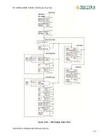
Page 47: ...PVI 3000S 4000S 5000S 5300 Series Inverters Installation and Operation Manual Rev A 47 Figure 6 3 1 LCD Display Flow Chart Solectria PVI 4000S ...

Page 48: ...ntact the installer or another qualified person to locate and repair the source of the ground fault Be aware that normally grounded conductors and equipment may be energized and may pose a significant shock and or fire hazard Weak Sunlight Condition Operation in weak sunlight for example early in the morning when overcast or when snow is covering most or all of the PV array can cause the inverter ...

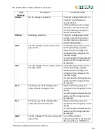
Page 49: ...enewables for assistance if the range needs to be adjusted VacL The AC voltage of mains utility is below the lower limit Verify setting for S201 is correct for the grid voltage applied Measure the AC voltage and compare to the voltage on the inverter display Contact Solectria Renewables for assistance if the range needs to be adjusted FacH The frequency of AC voltage of the utility is above the up...

Page 50: ...etween L1 and neutral is over the upper limit Verify setting for S201 is correct for the grid voltage applied Measure the AC voltage and compare to the voltage on the inverter display Contact Solectria Renewables for assistance if the range needs to be adjusted VacL1 L The voltage between L1 and neutral is under the lower limit Verify setting for S201 is correct for the grid voltage applied Measur...

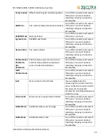
Page 51: ...system Immediately contact the installer or another qualified person to locate and repair the source of the ground fault DCInjectCurH Too much DC current injected into the AC grid is detected Turn off the inverter and restart If the error re occurs Contact installing company or Solectria Renewables VdcbusH Internal DC bus voltage is above the upper limit Turn off the inverter and restart If the er...

Page 52: ...U Delta The firmware version is not correct Internal measurement comparison error or defective hardware Turn off the inverter and restart If the error re occurs Contact installing company or Solectria Renewables GFDI CPU Delta Idc Turn off the inverter and restart If the error re occurs Contact installing company or Solectria Renewables IpvH Over current on the DC side Use a suitable meter for mea...

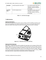
Page 53: ...efore replacement of the fuse you must switch off the DC AC disconnect switch and AC breaker and wait for at least 5 minutes for system to discharge GFDI Fuse OPEN Figure 7 2 1 Open Cap to Access the GFDI Fuse Replacing the PV String Fuses The inverter is shipped with four 4 15A 600Vdc PV string fuses for PV strings or three for PVI 3000S However the size of the PV string fuse is determined by the...

Page 54: ...easured voltage should be open circuit voltage If the measured voltage is at or close to 0 0V then STOP and do not remove any fuses Recheck your wiring to ensure there is not a dead short or a string with reversed polarity Check DC current of all strings using DC clamp on meter Measured currents should be at or very close to 0A If there is a measured current reading then STOP and do not remove any...

Page 55: ... the distributor or the dealer installer whichever is shorter If a warranty extension has been purchased the term is defined as an extension beyond 60 months For example if a 5 year extension to 10 years total is purchased the term becomes 120 months from date of purchase For the PVI 3000 to PVI 7500 inverters the warranty period is 120 months from the date of purchase by the end user or 124 month...

Page 56: ...cations Solectria Renewables will supply necessary parts as needed for warranty repairs however travel is not included Contact Solectria Renewables customer service for details on the freight policy for return shipments outside of the contiguous United States Canada and Mexico For single phase inverters 7 5kW and lower Solectria Renewables covers replacement inverters or parts necessary to repair ...

Page 57: ...bles provides technical assistance Monday Friday 8 30am 7pm EST and on call technical support is provided outside normal business hours What does the Solectria Renewables warranty not cover Solectria Renewables Limited Warranties do not cover normal wear and tear of the product or costs related to the removal installation or troubleshooting of the customer s electrical systems These warranties do ...

Page 58: ...A PARTICULAR PURPOSE OR ANY IMPLIED WARRANTY OF DISTRIBUTOR OR DEALER INSTALLER ABILITY ALL OF WHICH ARE EXPRESSLY DISCLAIMED TO THE FULLEST EXTENT PERMITED BY LAW ANY IMPLIED WARRANTIES OF MERCHANTABILITY OR FITNESS FOR A PARTICULAR PURPOSE OR ANY IMPLIED WARRANTY OF DISTRIBUTOR OR DEALER INSTALLER ABILITY TO THE EXTENT REQUIRED UNDER APPLICABLE LAW TO APPLY TO THE PRODUCT SHALL BE LIMITED IN DUR...

Page 59: ...TY OR LIABILITY FOR LOSSES DAMAGES COSTS OR EXPENSES WHETHER SPECIAL DIRECT INDIRECT CONSEQUENTIAL OR INCIDENTAL WHICH MIGHT ARISE OUT OF THE USE OF SUCH INFORMATION THE USE OF ANY SUCH INFORMATION WILL BE ENTIRELY AT THE USERS RISK WARNING LIMITATIONS ON USE Please refer to your product user manual for limitations on uses of the product Specifically please note that Solectria Renewables products ...

Page 60: ...the box b A return address to which the unit can be shipped Post office boxes are not acceptable c A contact telephone number where you can be reached during work hours d A brief description of the problem Ship the unit prepaid to the address provided by your Solectria Renewables customer service representative Returning a product from outside of the USA or Canada In addition to the above you MUST...

Page 61: ... temperatures you must make sure the MPPT voltage of the strings will not drop below the minimum inverter DC input voltage in very hot temperature conditions Both the maximum open circuit voltage OCV when at cold extreme and minimum MPPT voltage when at hot extreme can be calculated for a PV module using its specification sheet PV module string sizing can then be used to determine how many modules...

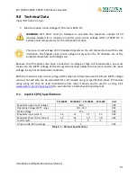
Page 62: ...EE Std 1547 2003 Table 1 Operating frequency and frequency range 60 59 3 60 5 Hz Maximum Continuous Current 13 5 16 8 21 15 22 1 Arms Output Current Protection 20 25 30 30 Arms Maximum Backfeed Current to PV 0 0 0 0 Arms Total Harmonic distortion THD full power 3 Power Factor Unity 0 99 Anti islanding protection per UL1741 IEEE1547 CSA22 2 107 1 FCC Part 15 B CEC Efficiency 240V 96 0 96 0 96 0 96 ...

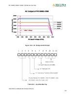
Page 63: ...PVI 3000S 4000S 5000S 5300 Series Inverters Installation and Operation Manual Rev A 63 Figure 9 3 2 DC Voltage and AC Output Table 9 3 3 Serial Number Key 7 8 digit Produce month MM 6 7 digit year YY ...

Page 64: ...om 10 5 Appendix E Positive Grounding Option See section 4 3 Connection of the DC wiring in the Wiring section for standard wiring for negatively grounded systems and refer to it while connecting for positively grounded systems using this appendix including use of all the warnings and cautions WARNING For positively grounded systems polarities of each DC input from a PV string shall be correctly c...

Page 65: ...DUCTOR terminal block Disconnect the red DC wires from PV array connected to UNGROUNDED CONDUCTOR terminal block o If using the bypass terminals disconnect the wires from the associated terminal block Connect the black DC wires from PV array to the UNGROUNDED CONDUCTOR terminal o If using the bypass terminals connect the black DC wires to this set of terminals Connect the red DC wires from PV arra...

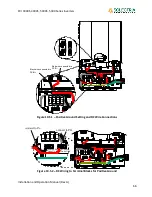
Page 66: ...4 JP14 JP15 JP15 Posit vi e ground Negative ground 1 1 Black wire connected to DCIN Red wire connected to DCIN Figure 10 5 1 Positive Ground Setting and DC Wire Connections Positv ie ground Negativ e ground 1 1 connect to PV UNGROUNDED CONDUCTOR GROUNDED CONDUCTOR Figure 10 5 2 DC Wiring to Terminal Blocks for Positive Ground ...

Page 67: ... on trackers or units installed outdoors fully exposed to elements and in climates where severe weather can occur Remove the 8 eight screws used to fasten the inverter cover It is not necessary to remove the inverter cover Open the wiring box and inverter cover Figure 10 6 1 Remove the Screws of the Inverter Cover Install the shields on the sides of the inverter and cover the air vents The larger ...

Page 68: ...feet length of wire PV panel mount Roof Pole Ground Solar tracker Yes No PV strings Output power Normal voltage range Vdc Peak open circuit voltage Vdc Normal current rating Adc maximum current rating Adc Number of panels Number of series parallel S P PV panel brand model Fault error information please write down exact words that appear on the LCD Fault message 1 on LCD Fault message 2 on LCD Faul...

Page 69: ...PVI 3000S 4000S 5000S 5300 Series Inverters Installation and Operation Manual Rev A 69 10 7 Appendix H UL1741 IEEE 1547 CSA22 2 107 1 Listing Letter ...

Reviews: