background image


ENG - 28 

03917101G.ENG    rev. 0 


(5) 

Water filter cleaning: 

 
It is important to fit between the engine and the bottom cock a filter 

to avoid that any imputities existing in these a water might clog the 

cooling conducts. 

 
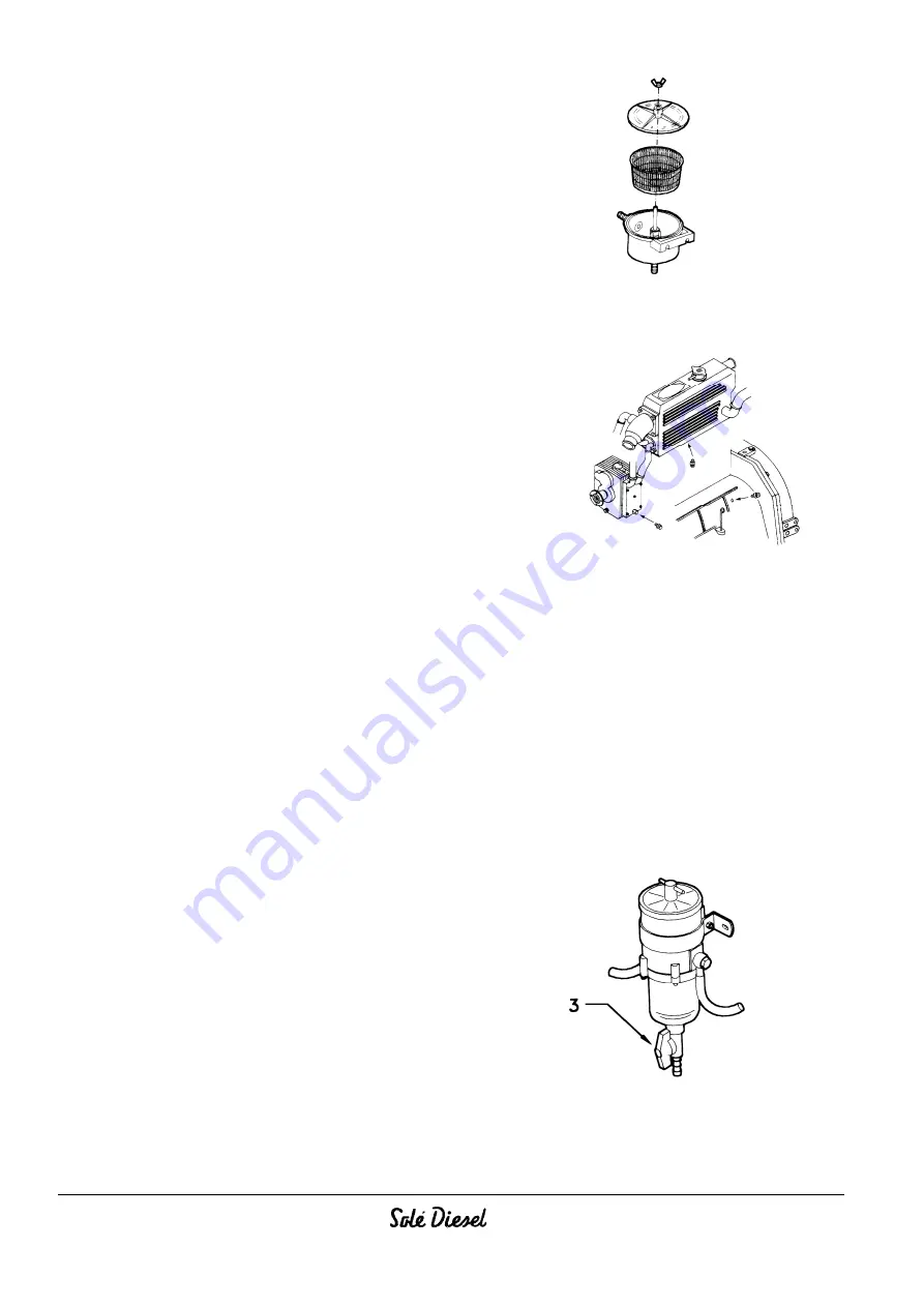
Filter shall be cleaned every 200 hours by loosening the wing nut 

and removing the filtering component. Clean the filter and fit it 

again taking care the cover is well seated on the O-ring (Fig. 7.4). 

Then the engine is started to check if water is leaking from the 
cover. 


Fig. 7.4 


(6) 

Change cooling circuit water: 


Drain off all the circuit water by opening the two drain cocks, one 

in the exchanger an other in the cylinder block (Fig. 7.5). 
 

When in cold climates, if the engine is not to be used for a long 

period, it is advisable to drain the water circuit. 

 
Once this operation has been completed, close the drain cocks 

and fill to the hole in the tank cap (see heading 4.2.2 of this 

manual). 


Fig. 7.5 


(7) 

Checking battery electrolite level and charge: 

Batteries require a very careful handling and frequent checkings. Proceed as shown below: 
 

(1) Always keep batteries dry and cleaned. 

(2) Regularly check terminal cleanliness. If dust is settled, terminals should be loosened, cleaned and smeared with a 

neutral grease layer. 
(3) Metal objects must not be placed over the battery. 

(4) Batteries or containers containing acids should carefully be handled. 

(5) Monthly or every 200 hours check the acid level and supplement it with DISTILLED WATER required. Level should not 

exceed the battery inside mark. 

(6) Never use open flames to light battery components: there is explosion danger. 
(7) In winter, batteries should be detached and placed following the manufacturer’s instructions. 


Before battery is charged with an external charger, disconnect both terminals.


(8) 

Fuel decanting filter drainage ( optional ): 


Loosen the wing nut (3) (Fig. 7.6) located at the lower side of the 

glass vessel and let go all the acrued water. Shut again off the 
wing nut and check it does not drip. 


Fig. 7.6 


Summary of Contents for G-20M-15

Page 1: ...INSTRUCTIONS MANUAL GENSET G 20T 15 G 20M 15 OPTIONAL CANOPY VERSION MARINE GENSETS...

Page 2: ...gar desde nuestra web www solediesel com o pedir a trav s mail oftec solediesel com Sol S A seeks for the constant improvement of its final products for that reason the design description dimension co...

Page 3: ...ON PUMP 2 5 ELECTRICAL PLANT 2 5 1 ELECTRICAL PLANT AND INTRUMENT PANEL 2 6 TECHNICAL SPECIFICATIONS ENG 9 2 6 1 ENGINE DIMENSIONS ENG 10 2 7 GENERAL INFORMATION ENG 12 3 TRANSPORT HANDLING AND STORAG...

Page 4: ...MPERATURES 6 5 CONSERVATION ENG 23 6 6 LONG INACTIVITY INSTRUCTIONS 6 7 RESTORATION OF THE RUNNING CONDITIONS 7 REPAIR AND MAINTENANCE ENG 24 7 0 GENERAL WARNINGS 7 1 TYPE AND FREQUENCY OF INSPECTIONS...

Page 5: ...perations illustrated in these pages If you run into difficulties or setbacks Service SOL DIESEL department will be proud to provide you with the necessary advice and assistance This INSTRUCTION MANUA...

Page 6: ...ASSES PROTECT RESPIRATORY PASSAGES MASK DANGER GENERAL DANGERSITUATION FOR THE SAFETY OF ANYONE AND PROTECTION OF THE ENGINE Danger Warning Attention Notices triangular General Attention regarding per...

Page 7: ...ine is designed and built as a power unit for generating mechanical energy ALL USES OTHERTHAN THE PRESCRIBED APPLICATIONAUTOMATICALLY RELEASE SOL S A FROMLIABILITY FOR DAMAGES THAT MAY ENSUE in any ev...

Page 8: ...ING EXHAUST GAS WHEN USING THE MOTOR IN A CLOSEDENVIRONMENT THE EXHAUST FUMES MUST BECONVEYED OUTSIDE 1 3 1 INFORMATION REGARDING RESIDUAL RISKS The engine must be used in compliance with the manufact...

Page 9: ...rolled by centrifugal pump with thermostatic control and heat exchanger Cooled exhaust collector Injection pump Type VE for engine part no 171 20 000 2 serial number 58182 Lubrication forced feed lubr...

Page 10: ...he filter the enginemain bearings and by way of external pipelines to the rocker arms Also read the heading 9 2 Oil circuit pressure with hot engine min 800 rpm 1 0 bar m x 2600 3000 rpm 2 4 bar 1 wit...

Page 11: ...2 5 ELECTRICAL PLANT 2 5 1 ELECTRICAL PLANT AND INSTRUMENT PANEL GET SET 1500 rpm Part No 1st Panel GET SET 1800 rpm Part No 1st Panel ENGINE TYPE GET SET 50Hz 60Hz 3 Phases 400V 230V 3 Phases 230V 1...

Page 12: ...ENG 8 03917101G ENG rev 0 CANOPY VERSION WITH FAN DELTA CONNECTION...

Page 13: ...ENG 9 03917101G ENG rev 0 STANDARD VERSION 3 PHASES 400V 230V...

Page 14: ...ENG 10 03917101G ENG rev 0 STANDARD VERSION 1 PHASE 230V...

Page 15: ...ter pump Liters h 2000 1 Para modelo motor base ref 17120000 2 Leer apartado 9 3 para otros motores MINI62 Consultar n de serie b GENERATOR UNITS Type Revolving field 4 poles Rigidly coupled to Enghie...

Page 16: ...ENG 12 03917101G ENG rev 0 2 6 1 ENGINE DIMENSIONS a GENSET 1 PHASE G 20M 15 b GENSET 3 PHASES G 20T 15...

Page 17: ...ENG 13 03917101G ENG rev 0 c GENSET G20T15 G20M15 CONEXIONES Taladros Anclaje Grupo...

Page 18: ...1 Dismantle the covers 2 mount the new pipes to connect the airvent Apply thread seallant on the racords 3 mount the hoses between outlet seawater pump and pipe 8 1 Connect a hose between the pipe 8...

Page 19: ...to the intended position of installation and remove the plastic wrap film Unscrew screws that secure the engine to the wooden base with draw the base and proceed with installation operations 3 1 3 PAC...

Page 20: ...TRANSPORT AND HANDLING OF THE UNPACKED ENGINE 3 5 STORAGE OF PACKED AND UNPACKED ENGINE If the engine is left idle for prolonged periods the client must check the possible conditions of conservation i...

Page 21: ...M22 3 0 5 0 6 0 22 0 36 0 43 0 Nozzle holder mounting bolts Glow plug Nut for B terminal of starter M10 M8 3 75 1 8 1 1 27 0 13 0 8 0 Reversing gear flange setscrew Water cooler element locknut Revers...

Page 22: ...evel and if it does not reach the top sign add carefully more oil through the filler hole Fig 4 2 up to the top rod sign Fig 4 1 Fig 4 2 Fig 4 3 Be careful that any rod marks refer to the engine at a...

Page 23: ...ions as indicate earlier The cooling liquid mixture must be topped up with identical mixture and totally drained and replaced every 2 years Warning The use of coolants that are not in conformity with...

Page 24: ...ll be formed thus reducing engine power output and obstructing proper cooling In these cases it is advised to take steps to avoid taking in engine combustion air from the place in which the engine is...

Page 25: ...b FILLING WITH COOLANT See heading 4 2 2 c REFUELING See heading 4 2 3 Check fuel delivery cock is fully opened d OPEN SEAWATER ENTRY COCK e CONNECT THE BATTERY CONNECTOR f REMOTE CONTROL CONNECTION f...

Page 26: ...oceed to start the engine see the heading 6 1 Warning Protect hands Fuel can harm the skin 5 2 PRELIMINARY RUNNING TESTS 5 2 1 NO LOAD RUNNING TEST Run the engine at low speed for a few minutes Keep a...

Page 27: ...the sea water filter cover and start the engine adding a mixture of fresh water and 30 anti freeze until the sea water circuit is filled completely Stop the engine and replace the sea water filter co...

Page 28: ...m will be filled with anti freeze mixture Stop the engine 5 Use a dielectric spray on the electrical connections disconnect the battery and charge it several times during the period of inactivity 6 7...

Page 29: ...LOTHING IT IS STRICTLY FORBIDDEN TOCLEAN THE ENGINE WITH COMPRESSED AIR IT IS STRICTLY FORBIDDEN TOPERFORM MAINTENANCE CLEANING OPERATIONS IN THE PRESENCE OF MOVING PARTS USE GLOVES OVERALLS ETC TOPRO...

Page 30: ...ter is flowing and if some failure is detected in the exhaust gases noise and vibrations Overhaul of the propeller shaft and positioning screw tightening torque Check cooling water level Clean water f...

Page 31: ...Intake valve play 0 25 mm Exhaust valve play 0 25 mm With piston n 1 in the top dead centre of the compression cycle adjust the play of the intake and exhaust valves of cylinder n 1 Proceed similarly...

Page 32: ...2 of this manual Fig 7 5 7 Checking battery electrolite level and charge Batteries require a very careful handling and frequent checkings Proceed as shown below 1 Always keep batteries dry and cleaned...

Page 33: ...such a change loosen filter center nut remove the cover and filtering component by replacing with a new one The component CANNOT be cleaned it must be changed Fig 7 7 Fig 7 7A Change air filter See th...

Page 34: ...pressure gauge If measurement of any cylinder is below 28 Kg cm2 at 200 rpm the cylinder must be repaired Difference in pressure between cylinders must be within 2 Kg cm2 18 Inspect injection pump The...

Page 35: ...CORRECTLY OR SEIZED C6 OIL LEVEL TOO LOW L6 INJECTION PUMP INCORRECTLY SET C7 FAULTY OIL PRESSURE VALVE L7 WATER IN FUEL SYSTEM C8 FAULTY OIL PRESSURE GAUGE OR SWITCH L8 FUEL OUTLET COCK CLOSED C9 OI...

Page 36: ...components of the engine are made contact SOL S A 8 2 DERATING OF ENGINE DUE TO FUEL AND COMBUSTION PROPERTIES FUEL PROPERTIES Output correction due to fuel properties Specified outputs presuppose the...

Page 37: ...air deviates from these values correction factors in are found in the graphs below Use the correction factors in calculation of engine output Output correction Output correction Temperature C Air Pre...

Page 38: ...1 INT EXHAUST HOSE 2 BATTERY 12V CABLE TO BATTERY LENGTH m MINIMAL SECTION CABLE TO BATERRY INT FUEL HOSE FROM TANK TO PRIMING PUMP mm INT FUEL HOSE FROM INJECTION PUMP TO THE TANK mm MINI 62 180 230...

Page 39: ......

Page 40: ...GENSETS SOL S A Dpto Publicaciones T cnicas Ctra Martorell a Gelida km 2 C 243b 08760 Martorell Barcelona Spain Tel 34 93 775 14 00 Fax 34 93 775 30 13 e mail sole solediesel com www solediesel com R...

Reviews: