


18
ATTENTION!
Install a model B leakage current protection switch with no less than 600 mA
current. Do not share neutral wire when B leakage current protection switch is
installed or else a power grid trip may occur.
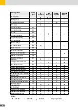
AC output cables requirements
For AC power cables outdoor multi copper-cores cables are recommended. For the specifica-
tion of these cables see the following table:
Inverter
Cable Type
Cross-sectional area (mm
2
)
Cable Outer
Diameter (mm)
Range
Recommended
Range
17SHT, 20SHT,
22SHT
Multi-core
outdoor cable
6 … 16
10
24 … 32
25SHT, 28SHT,
30SHT
10 … 25
16
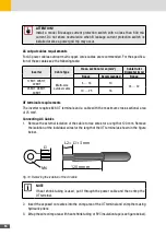
OT terminals requirements
The inverter requires M6 OT terminals and a cable with the maximum cross-sectional area
of 25 mm
2
.
Connecting AC Cables
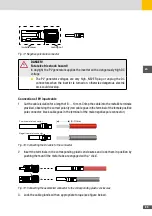
1. Remove the external isolation of the cable to free wires for a length of 120 mm. Remove
the isolation of the individual wires for the length of the OT terminal as shown in the figure
below.
L2 = L1+3 mm
120 mmm
L1
M6
Fig. 10: Removing the isolation of the AC cable
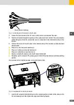
NOTE
If heat shrink tubing is used, put it through the power cable and then crimp the
OT terminal.
2. Insert the exposed core wires into the crimp area of the OT terminal and crimp them using
hydraulic pliers
3. Wrap the wire crimp area with heat shrink tubing or PVC insulation tape (see figure below).
Summary of Contents for 17SHT
Page 1: ...Instruction Manual SolarMax SHT series 17SHT 20SHT 22SHT 25SHT 28SHT 30SHT...
Page 4: ...4...
Page 39: ...39 en...


