


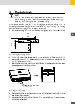

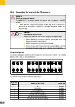


22
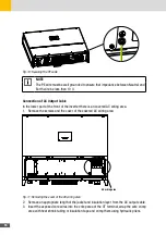
Connection of PV input cable
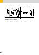
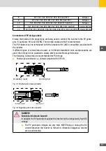
1. Cut the cable isolation for a length of 8 … 10 mm. Crimp the cable into the metallic terminals
provided, observing the correct polarity (red cable goes in the terminal of the female positive
pole connector; black cable goes in the terminal of the male negative pole connector).
Positive metal connector
Negative metal connector
Fig. 17: Connecting the DC cable to the connector
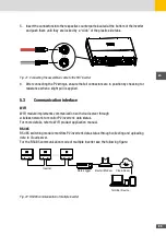
2. Insert the terminals in the corresponding plastic enclosures and lock them in position by
pushing them until the metal tabs are engaged with a “click”.
Fig. 18: Connecting the assembled connector to the corresponding plastic enclosures
3. Lock the cable glands with an appropriate torque (see figure below).
Fig. 19: Locking the cable glands
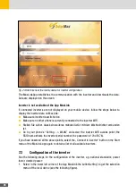
4. Check with a voltmeter of proper scale that the polarities and the DC voltage values are
correct.
RANGE
MAXMI N
REL
Hz %
P
C
800 00
Fig. 20: Checking DC voltage values with a voltmeter
Summary of Contents for 10260200
Page 1: ...Instruction Manual SolarMax SHT series 50SHT 60SHT...
Page 4: ...4...
Page 39: ...39 en Notes...


