background image

6

STEP 4: Connect to the Battery or Battery Bank

A. Be sure the charge controller is set to the correct battery type. Do this by selecting either 
    Lead-acid’ or ‘Gel’ using the switch on the back. For acid flooded wet cell batteries use the 
‘    Lead-acid’ setting. For sealed Gel batteries use the ‘GEL’ setting.  For sealed Absorbed Glass 
    Mat (AGM) batteries, use the ‘Lead-acid’ setting.  
B. Unfurl the 16’ cord and attach the appropriate battery connection adapter.  The ideal use of 
    each type is described earlier. Note the location of the in-line fuse.
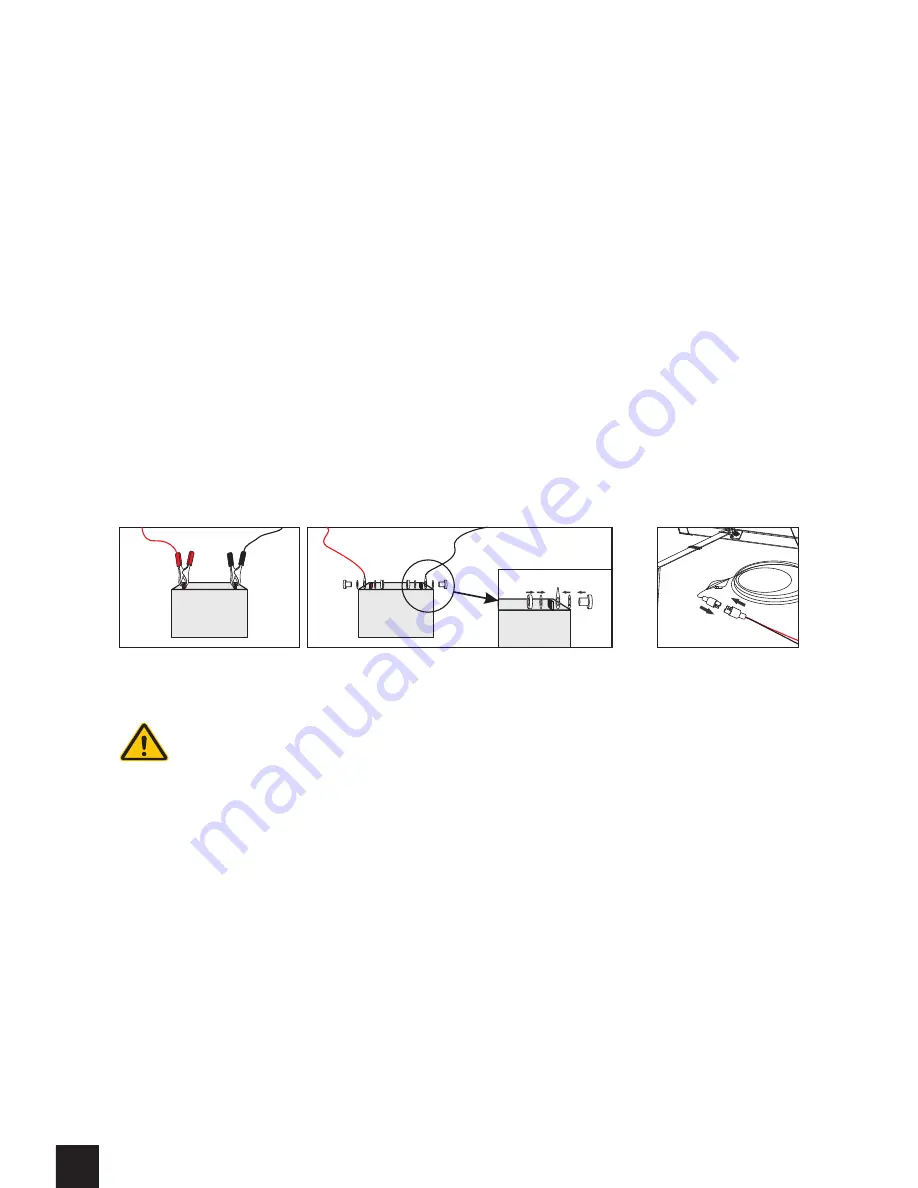
C. When using the Battery Clips or the Ring Terminal Adapter, make the connections directly to 
    the battery terminals. IMPORTANT: OBSERVE POLARITY. This means you must be careful to 
    attach the red wire to ‘Positive’ or ‘+’, and the black wire the ‘Negative’ or ‘-’. If polarity is reversed 
    accidentally, no permanent damage will occur, but the in-line fuse will blow. In this case, correct 
    the polarity and replace the fuse. 
D. It is generally considered ‘good practice’ to remove the batteries from the vehicle when 
    charging. This is because dangerous Hydrogen gas, given off by many types of batteries while 
    being charged, can build up inside confined spaces which could explode under certain 
    conditions. However, removal of the battery from the vehicle is not necessary provided the 
    battery is being charged in a well ventilated area. A well ventilated compartment, or a battery 
    bank tray that has good ventilation to the outside air, is adequate for charging the battery while 
    installed.
E. When connecting to a multi-battery system or ‘battery bank’, see section 10 for specific details. 
F. It is best to attach the Portable Solar Panel System to the battery or battery bank at the 
    beginning of each camping event rather than to wait until the battery is dead before connecting. 
    This allows the Solar Panel System to ‘keep-up’ with the loads on the battery and fully charge it 
    each day. This leads to longer overall battery life and better electrical system operation. 

The battery wire is first connected to battery.

Battery Clamp

Ring Terminals

There will be no power output from the Charge Controller until the unit is 
connected to the battery.  

When the Portable Solar Panel System is first connected to a battery or battery bank, and the 
panels are exposed to full sun, the charge controller undertakes a self-check and configuration 
routine.  In some cases this may take up to 3 minutes during which the LED’s on the charge 
controller will not be illuminated and the battery will not be receiving any charge.  Once the 
configuration and self-check procedure is complete, the system will engage, the charging process 
will commence, and the Yellow LED will illuminate.

Summary of Contents for SLP090F-12S

Page 1: ...USER MANUAL Model SLP090F 12S and SLP130F 12S The Portable Folding Solar Battery Charging System...

Page 2: ...Functions 2 Features 3 Components 4 Specifications 5 Installation Connection 6 Display Functions in normal operation 7 Trouble shooting Guide 6 Safety Recommendations 9 Frequently Asked Questions 10 T...

Page 3: ...es and devices RV s Boats and Marine Trailers horse and travel Cabins and Cottages Construction and farm equipment Material Handling equipment Camping Automotive Aircraft ATV and Snowmobile Motorcycle...

Page 4: ...es such as cell phones or laptop computers have electronic circuitry between the device and the cigar lighter plug This circuitry can sometimes prevent the Solar Charge Controller from activating If y...

Page 5: ...ic smart solar change controller Rubber Corner Protector Heave duty anodized aluminium folding support leg Adjustable belt for support legs Tent stake Heavy duty ABS handle 16 cable with heavy duty ma...

Page 6: ...Voltage Max Charge Voltage Charge Restart Max Solar Panel Current Max Load Current Self Consumption 10A 10A In line Fuse Type Standard Glass Automotive Rated 10A 32V Recomended Batteries not included...

Page 7: ...is to tilt the solar panel up and down and observe the shadow it casts behind it Lock the tilt legs in place when the tallest shadow is observed This ideal time to make this adjustment is at 12 00 no...

Page 8: ...the battery from the vehicle is not necessary provided the battery is being charged in a well ventilated area A well ventilated compartment or a battery bank tray that has good ventilation to the outs...

Page 9: ...9 and 14 4 indicating the battery is fully charged temperature dependent This condition will continue for approx 2 hours before the float mode engages Green Battery full The Charge Controller has ente...

Page 10: ...store operation by reconnecting to the battery If the yellow light on the charge controller does not illuminate contact your Solarland dealer immediately for assistance The CHARGING LED does not glow...

Page 11: ...arging an old damaged overly discharged defective battery 13 When testing or working on or around a battery it is advisable to wear protective eye glasses 14 Have plenty of fresh water soap available...

Page 12: ...n to the equation to account for losses due to resistance and other system inefficiencies If a typical 100 Ah deep cycle RV Marine battery is used this equates to about 43 6 depletion daily and is ade...

Page 13: ...6V 6V 6V 6V Chassis Ground Load Load Load Shunt Shunt Fuse Fuse To Inverter Charger To Inverter Charger To Accessory Loads To Accessory Loads CORRECT CORRECT Typical Series Parallel RV Installation T...

Page 14: ...Series Parallel RV Installation Liability Exclusion The manufacturer shall not be liable for damage especially on the battery caused by use other than as intended or as mentioned in this manual or if...

Page 15: ...gh tech Industrial Area Wuxi 214028 Jiangsu P R China Tel 86 510 82261100 Fax 86 510 85203812 www solarland com info solarland com Chicago Office PO BOX 6128 Lindenhurst IL 60046 USA Tel 847 282 4796...

Reviews: