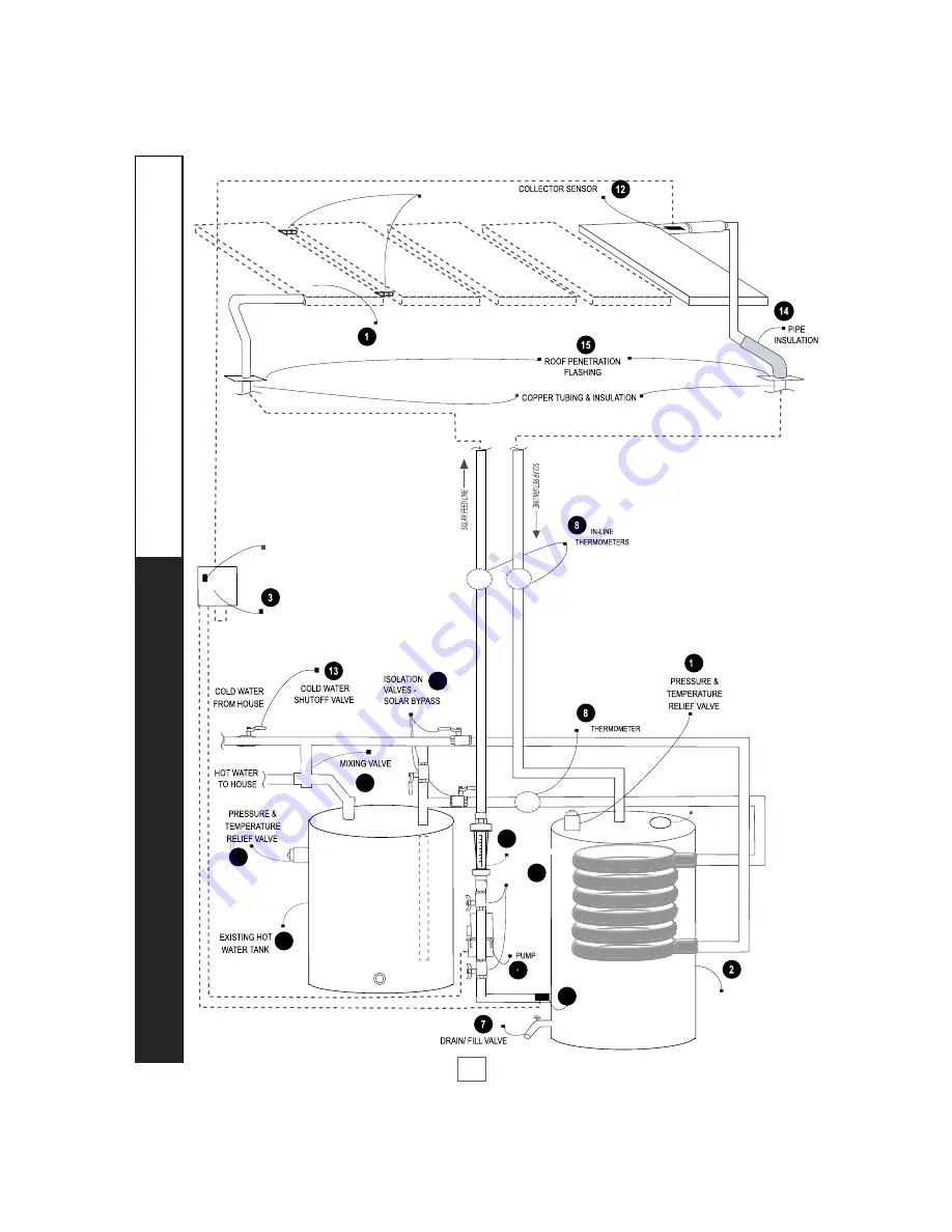
Solar Heat Exchange 80SDB-XE-Suntask 1 Installation And Owner'S Manual Download Page 19

DIFFERENTIAL
TEMPERATURE
CONTROLLER
120V

SIMPLE DRAINBACK
TANK

TANK SENSOR (T2)

6

PUMP
ISOLATION
VALVES

SOLAR

9

10

11

T1

HOT WATER

4

FLOWMETER

MG ANODE

SHEM DHW SYSTEM SCHEMATIC

-XG GAS BACKUP TWO TANK  CONFIGURATION

ON/OFF BUTTON

17

18

5

6

18

SOLAR

COLLECTORS (1-5)

1”  SWEAT COUPLINGS

OR UNIONS

Summary of Contents for 80SDB-XE-Suntask 1

Page 1: ...TPP24 2 80SDB XE VHP30 1 80SDB XE VHP30 2 INSTALLATION OWNER S MANUAL SOLAR MADE SIMPLE SHEM IOMSDB 4 16 13 Solar Heat Exchange Manufacturing The solar energy system described by this manual when pro...

Page 2: ...e Solar energy is safe and reliable and your decision to use solar energy is helping to preserve our environment and to reduce our rapid depletion of non renewable fossil fuels Your new SHEM Solar Hot...

Page 3: ...e collectors and or piping from bursting at low temperatures WARNING THE COLLECTORS AND PIPING MUST DRAIN COMPLETELY TO PREVENT FREEZING A SLOPE OF 1 4 INCH PER FOOT OF RUN IS REQUIRED CAUTION FILLED...

Page 4: ...tional tank kicks on and heats the water to the desired temperature 4 DIFFERENTIAL SOLAR CONTROL temperature of the water in the Storage Tank and how much heat is available in the Solar Collector If h...

Page 5: ...Secure ladders so they will not slip or fall Wear shoes with proper tread to prevent slipping on the ladder or sloped roof areas cal hook ups especially when water is present It s always a good idea...

Page 6: ...ler or disconnect the power to the circulation pump and then isolate the solar system utilizing the solar bypass valves Call your dealer right away for service Diagrams 1 2 detail how to enable and by...

Page 7: ...The pipes between the tank and the collectors MUST be insulated with at least 3 4 thick insulation for the same reason The solar collectors must be located in a structurally sound area of the roof tha...

Page 8: ...o the roof make sure that the weep holes are facing down It is recommended to install the collectors vertically length up the roof s slope 2 Once the collector s location is determined anchor two 2 Mo...

Page 9: ...on should guide the manifold into the coupling while using the channel lock to turn and properly locate the coupling The other person is easing both the top and bottom manifolds together in small alte...

Page 10: ...ting clips to the BOTTOM part of the collector the weep hole side using two 2 stainless steel or aluminum screws each Picture 7 3 Assemble both rods and top mounting clips Picture 8 Connect the clips...

Page 11: ...ation an Insulation Jacket is recommended Frost King or equal Be careful not to cover the thermostat access panels or the P T ports if additional insulation is required PLUMBING CATCH PAN DIAMETER OF...

Page 12: ...t to 120 F The temperatures generated by your Simple Drainback System will vary throughout the year In the Northern Hemisphere the water temperature will be hottest in the spring and summer months whi...

Page 13: ...t joints must be sealed with contact adhesive The use of rigid polyethylene pipe insulation is prohibited All outdoor insulation should be protected from moisture and ultraviolet deterioration by eith...

Page 14: ...supply line and one on the return line of the solar loop so that the temperature rise across the collector can be determined 8 in the system schematics DRAIN FILL VALVE Install a 3 4 drain fill valve...

Page 15: ...e tank and place the other end in a 5 gallon bucket or sink 2 Connect another hose to the Drain Fill Valve and the other end to a spigot and open the Drain Fill Valve 4 Close the Drain Fill Valve and...

Page 16: ...eater adding solar energy when and as available or 3 100 on utility power during inclement weather Total Solar Operation trippers from the face of the switch The solar bypass should be set to enabled...

Page 17: ...4 Mixing Valve tempers temperature of hot feed line to home and should be installed at the outlet of the existing conventional hot water tank 10 Pressure Temperature Relief Watts 100XL 4 P T Relief V...

Page 18: ...DRAINBACK TANK TANK SENSOR T2 6 PUMP ISOLATION VALVES SOLAR 9 10 11 T1 HOT WATER 4 FLOWMETER MG ANODE SHEM DHW SYSTEM SCHEMATIC XE ELECTRIC BACKUP TWO TANK CONFIGURATION ON OFF BUTTON 17 18 5 6 17 SO...

Page 19: ...PLE DRAINBACK TANK TANK SENSOR T2 6 PUMP ISOLATION VALVES SOLAR 9 10 11 T1 HOT WATER 4 FLOWMETER MG ANODE SHEM DHW SYSTEM SCHEMATIC XG GAS BACKUP TWO TANK CONFIGURATION ON OFF BUTTON 17 18 5 6 18 SOLA...

Page 20: ...where from 15 to 20 years or more depending greatly upon regional wa Control and Solar Pump life expectancies run from 5 to 10 years As electrical components they are susceptible to lightning strikes...

Page 21: ...ce these labels on Solar Feed and Solar Return Lines Place this label on Manual Drain 7 Place these labels on Solar Pump 6 Simple Drainback Tank 2 and Mixing Valve 9 WARNING HOT WATER Fluid may be dis...

Page 22: ...n the Drain Valve Allow the water in the Simple Drainback Tank to drain into a sink or a location outside CAUTION WATER MAY BE EXTREMELY HOT Maximum Operating Temperature 210 F Pressure 29 PSI Freeze...

Page 23: ...lines and it comes equipped with an anode rod which prolongs tank life Your new solar storage unit is fed from the existing cold water inlet which your existing conventional tank used This water enter...

Page 24: ...drops With this valve installed the solar loop pressure cannot increase to the potable water pressure in the heat exchanger Therefore the solar fluid cannot backflow into the higher pressure domestic...

Page 25: ...olar pump on and off at the appropriate temperatures When switched to OFF the control turns the solar pump off The Automatic Control has a high limit storage setting that can be adjusted from 110 F to...

Page 26: ...ines in your system can verify this differential Pushing the buttons will also change the Controller display from T1 collector to T2 Tank temperatures 3 The water in the bottom of the backup water tan...

Page 27: ...ain Fill Valve 7 Attach another hose to the P T Valve port 16 in the top of the tank and place the other end in a sink or 5 gallon bucket Open the Drain Fill Valve 6 Turn on the water to the garden at...

Page 28: ...realize that the water in the solar loop can be VERY HOT charged properly follow the steps outlined in System Start Up INDICATORS OF PROPER OPERATION The Simple Drainback system provides direct and i...

Page 29: ...lt should be exceptionally long system life Rust from condensation on the outside of the bottom of the tank represents the single greatest danger to tank life Be sure to install the tank up off the fl...

Page 30: ...mit The central ingredient providing freeze protection to your system is utilization of the drain back design which allows all of the water in the Solar Collector and solar loop to drain back to the S...

Page 31: ...the factory input alteration of the tank s design in any way including but not limited to the attachment of non company approved appliances or equipment Any accident to the water heater or any part t...

Page 32: ...K OR THE INSTALLATION OPERATION REPAIR OR REPLACEMENT OF THE TANK OR PARTS THE WARRANTOR SHALL NOT BE RESPONSIBLE FOR WATER DAMAGE LOSS OF USE OF THE UNIT INCONVENIENCE LOSS OR DAMAGE TO PERSONAL PROP...

Page 33: ...material or workman the published collector list price at the time the replacement is required Exceptions cally stated in this warranty statement Neither SOLENE LLC its dealers nor its distributors s...

Page 34: ......

Page 35: ......

Page 36: ......

Reviews: