SOFTLINK Sigfox WS868-PLE-I Manual Download Page 11

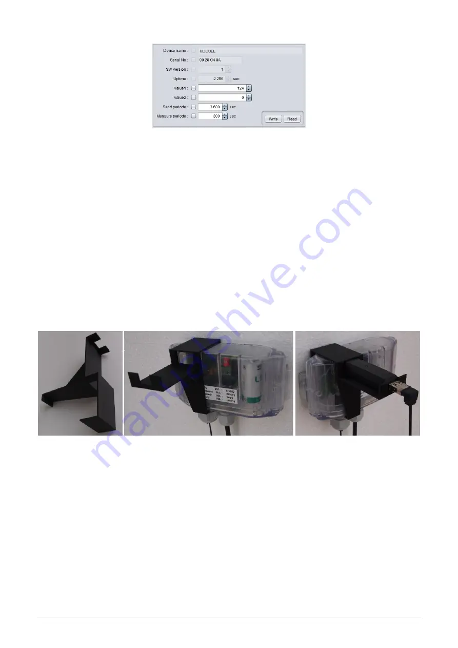
Figure 10: Example of module’s configuration table in the

WACO OptoConf” window

3.2.4

General rules for configuration of the module by optical converter

Connect

USB-IRDA

optical converter to the USB port of the computer. Flashing of green LED signalizes correct

function of the converter. By clicking to

optoconf.jar” file (or its shortcut) launch

WACO OptoConf”

program.

If not chosen automatically by previous functioning, choose the name of serial port of the converter (

COM XY”)

in the

Config/port” menu.

Configuration can be performed either on the working desk or with using of a special holder for attaching of optical
converter to the module.

Configuration on the

working desk

means that computer as well as the module are placed on the any convenient

work surface (e.g. on the desk - see figure

6

). In this case the module should be placed not more than 15 cm from the

tip of converter, the module’s printed board must be facing to converter by its element side, and module’s optical
sensor should be lying approximately in the converter’s axis of symmetry (i.e. in the direction of the infrared beam).
Approximate position of the optical sensor of the module is marked in the figure

1

by green arrow. Correctness of

mutual position module/converter can be checked by displaying of the current configuration as described below. It
is necessary to fix and keep such position in which the communication between module and converter is reliable.

When working directly at the installation site always use

a special holder

that is designed for attaching of converter

to the module. Put the holder to the WS868-PLE-I module as shown in the figure

11

.

Figure 11: Attaching of optical converter to the holder

Put holder to the module from the element side and shift it to that side where the optical sensor is placed (approx-
imate position of the optical sensor is marked in the figure

1

by green arrow). Connect the converter with laptop

by using of extension USB cable and insert the converter to the slot in the holder as shown in the picture. Check
correctness of converter’s position by displaying of the current configuration as described below. If the connection
is not reliable shift the holder along the module’s cover. The best position is if the converter is right opposite to
sensor.

By clicking to

Read device”

open a configuration table with all the relevant parameters of the module. Parameters

that can be changed are displayed in white colored editing fields. There are four types of editing fields:

- text fields, in which a text can be edited (e.g. ”Info-text” field)
- numeric fields, in which a change of number can be done
- selection fields, in which a choice from pre-set options can be done
- hexadecimal fields (marked by ”hex”), in which hexadecimal characters can be entered

Text fields

can be changed by correcting, erasing, or rewriting of the text inside the field.

Numeric fields

can be changed by rewriting number inside the field or by its increasing/decreasing with using of

WS868-PLE-I

8

Summary of Contents for Sigfox WS868-PLE-I

Page 1: ...WIRELESS COMMUNICATION SYSTEM Sigfox WS868 WS868 PLE I Revision 1 0 SOFTLINK s r o Tomkova 409 278 01 Kralupy nad Vltavou Czech Republic Phone 420 315707111 e mail sales softlink cz www softlink cz...

Page 2: ...of WS868 PLE I module parameters by configuration cable 13 3 5 1 List of WS868 PLE I module configuration parameters and commands 13 3 5 2 Commands for saving of configuration parameters and reset 13...

Page 3: ...erter 6 7 Displaying of the optical converter in the Windows Device Manager 7 8 Displaying of WACO OptoConf configuration window 7 9 List of variables in the working window of WACO OptoConf program 7...

Page 4: ...network server to the application servers of authorized users through the unified data interface via public Internet 1 2 Module usage The WS868 PLE I module can be used for remote reading of Elster BK...

Page 5: ...ynchronous Transmission parameters 8 data bits 1 stop bit none parity Signal level TTL CMOS Optical configuration interface Transmission speed 115 200 Baud Optical interface specification IrPHY 1 4 st...

Page 6: ...e to computer Configuration can be performed by using of common USB port of the computer For the interconnection with a USB port of computer it is necessary to use a manufacturer s original configurat...

Page 7: ...nal setting for serial line communication PuTTY software runs after clicking on the downloaded file putty exe There will open a window of the terminal communication see Figure 4 For switching the prog...

Page 8: ...ers HELP enter question mark or and press ENTER key when entering characters distinguish strictly the capital and small letters according to the documentation or HELP Do not enter other characters tha...

Page 9: ...ow 3 2 2 Connection of USB IRDA optical converter to computer Before starting of the WACO OptoConf program connect the USB IRDA converter to USB port of the computer When the converter is connected to...

Page 10: ...ystem communication systems can be found on the producer s WEB site NEP Page By clicking to Read device button the textbfconfiguration table with all the relevant parameters of the module is displayed...

Page 11: ...n between module and converter is reliable When working directly at the installation site always use a special holder that is designed for attaching of converter to the module Put the holder to the WS...

Page 12: ...s either bad position of the module long distance wrong orientation dirty cover obstacle in the beam or the module s battery was switched off NOTE WACO OptoConf program contains specific data and sett...

Page 13: ...ce see figure 13 left Figure 13 Displaying of the device without driver in Device Manager window By right clicking to USB Serial port open the context menu and choose Update driver software item Click...

Page 14: ...d Boot Options appears choose Disable Driver Sig nature Enforcement option in this window after launching the system install the driver according the above mentioned instructions Deactivation of the e...

Page 15: ...g to the above described procedure Deactivation of the enforcement of signed driver function of the Windows 10 operating system is functional only until the next restart of the system 3 4 3 Support of...

Page 16: ...M enable mode setup on startup ppm set Xtal ppm s sec set sending time in seconds m sec set measure time in seconds d n n th uplink message has downlink capability 0 no downlink i index value set init...

Page 17: ...broadcasting period The period is set in seconds and the module broadcasts its INFO messages spontaneously with this period Example of setting of broadcasting period to 1 hour 3600 seconds and corres...

Page 18: ...utput value counter value multiplier i index d value setting of divisor output value counter value divisor Important note The first input with index 0 that registers revolving of gas meter pivotal whe...

Page 19: ...initialization mode Mode setup Do not use Only for factory setting ppm enteering of XTAL correction constant Do not use Only for factory setting D number debug statement switch on Do not use Only for...

Page 20: ...t based on suspension cause 2 means Watchdog reset reset by watchdog system 3 means Error reset incorrect instruction or inconsistent data 4 means Power reset caused by low power voltage The parameter...

Page 21: ...nf program window View of configuration table is depicted in figure 16 Figure 16 The WS868 PLE I module configuration table In the upper section of the table there are read only type of parameters fac...

Page 22: ...ontract that is valid for configured device The Measure periode parameter is used for setting of analog quantities temperature voltage measurement interval in seconds More detailed description of this...

Page 23: ...7 Structure of module data messages The WS868 PLE I module is intended for reading of data from Elster gas meters of BK G series and broadcasting of measured data through the Sigfox RF network Maximu...

Page 24: ...capacity reduces frequency of broadcasting 4 2 The condition of modules on delivery Modules are delivered in standard cardboard boxes The modules are commonly delivered in fully operating status with...

Page 25: ...de of the module should be locked inside the gas meter lock connect module sealing protrusion with matching protrusion on the gas meter by sealing screw or sealing wire or other prescribed way and sea...

Page 26: ...as meter counter status and seal number Fill in the prescribed service documentation If possible arrange making of all appropriate changes in the database of the remote reading system immediately 4 8...

Page 27: ...y batteries used in the wacoSystem modules that have been carefully selected and properly tested In case of battery replacement by user the new battery parameters should meet same technical requiremen...

Page 28: ...ce these elements for the spare ones with proven functionality check correctness of module settings and perform the check of module overall functionality as described in paragraph 4 9 replace the modu...

Page 29: ...nfiguration options of WS868 PLE I RF modules designed for operation in Sigfox IoT network in868 MHz frequency band that are a part of the Softlink s wacoSystem product family More information about a...

Reviews: