


24
EN
5
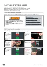
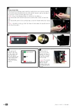
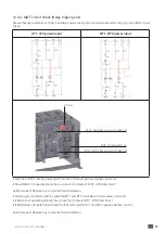
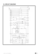
Connected position
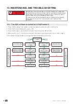
This is the normal operating position with the transfer switch main circuit connected.
* # %$$ ($# 1# 9 $ # 55 %$$A !%# ! # ( $ 7
( ! @ " 1# %$% 2 # "
!$ I
* "!% & $2 ( $! @ $% !%# !
+!%# # %2 %($"# $%$ # D !$ # ( $( ! @ 2%
1")
+!%# # %2 %($"# $ D !$ # ( $( ! # "#% # ")$&
pin.
!$ I
# ($"# ($ & # 2! ($ " 8"": ($#
9 $ # %$$
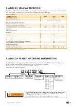
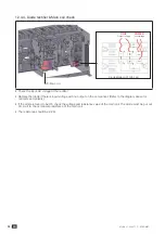
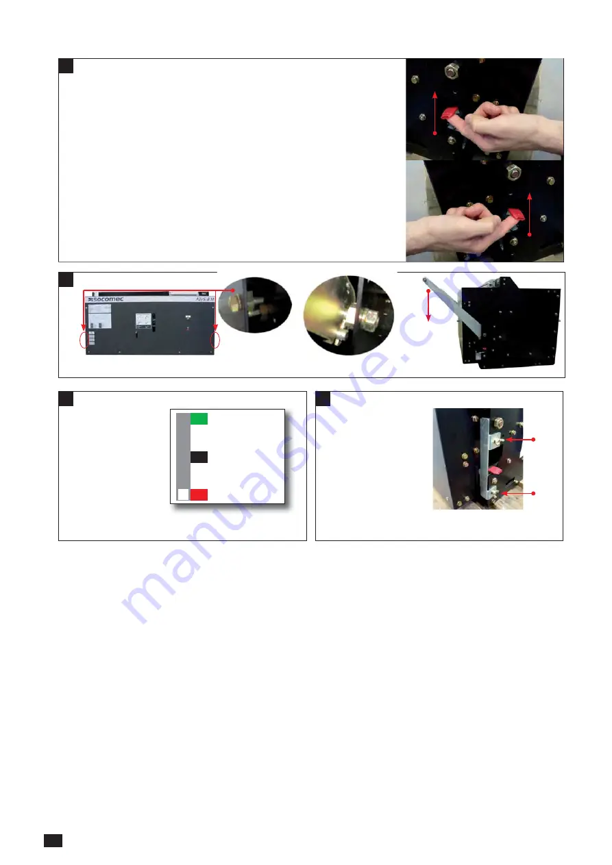
6
7
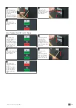
After pushing the
transfer switch fully
$ # "A !%#
down the draw in-
( ! #A
"#") # # (
in/out indicator is
$ # "
position.
Disconnected
Test
Connected
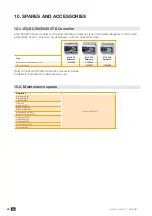
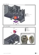
8
After the draw in
"$ $% "A
" # "@ 2
# ( $! @
D6 # 1!v
!% 8 !%:
!$I
The transfer
switch may draw
itself out due to
@$1$ $2 # "@
$% D6 $&# %
shown.
Summary of Contents for 95333400
Page 32: ...31 EN 12 4 12 4 1 F p F Z Z I 9I I 1 I 2 9 9 9 1 1 9 1 1 B 1 7 1 A 2 B 1 7 1 9 9 A 9 2 ...
Page 35: ...34 EN 12 4 4 F c q I COIL POWER 4 I 44 5 3 B 2 D B 2 8 2 1 2 B 2 2 1 W 2 1 2 2 B 1 ...
Page 38: ...37 EN 12 6 2 Parts name 3 L6 12 6 3 Parts name L 9 3 36 3 36 _ X x 2 ...
Page 39: ...38 EN 12 7 X 1 H D G 1 1 ...
Page 40: ...39 EN 13 CIRCUIT DIAGRAM ...
Page 42: ...41 EN ...


