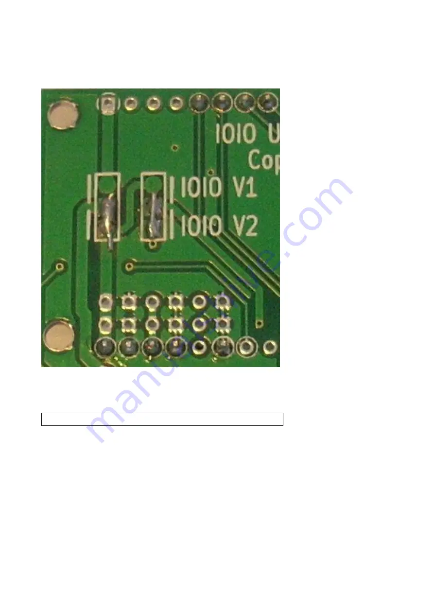
Connect solder points in the backside of the PCB as shown in this image.
Solder connections made in image are for IOIO OTG card
Page 1: ...Soartronic IOIO UART interface v2a assembly manual for IOIO OTG www soartronic com...
Page 2: ...o build Soartronic IOIO interface v2a for use the IOIO OTG card This PCB can also be used with IOIO version 1 however if assembled using these instructions this board will not work as expected and the...
Page 3: ...ing electrical components Follow these instructions and solder all other components before the IOIO board Place coil 100nF capacitor and two electrolyte capacitors please note electrolyte capacitors h...
Page 4: ...Place three diodes these are also polarity parts place them as shown in image...
Page 5: ...Place two max232 s RJ45 connectors and ten capacitors capacitors are either 100nF or 1uF depending version of max232 Now your PCB should look like this...
Page 6: ...Place pin headers for IOIO card as shown in images below THIS IS IMPORTANT For IOIO OTG do NOT add any extra pins...
Page 7: ...Connect solder points in the backside of the PCB as shown in this image Solder connections made in image are for IOIO OTG card...
Page 8: ...older the IOIO card The USB connector should point into the opposite direction with the RJ45 connectors and all the components and the USB connector should be on the TOP You need to have this kind of...